|

Stealth Ram Intake Install (March 6, 2013)
This page documents the installation of a Holley Stealth Ram intake. I purchased the intake used off of an engine that caught on fire. The fittings were shot and the polished intake was stained. I went with the intake because I felt it would match the powerband of my 327 engine better. I am using my modified factory TPI computer with a factory throttle body with this intake.I also upgraded the cam to the Competition Cams Hydraulic Roller XFI cam (268XFI). This advertised duration is 268 int./280 exh with with the following lift numbers: 0.520 int./0.515 exh. The basic operating RPM range is 2,000-6,000 rpms and should work nicely with the Holley Stealth Ram intake. I got the full kit including springs and retainers and installed them as well.
Status photos as of 3/3/2013:
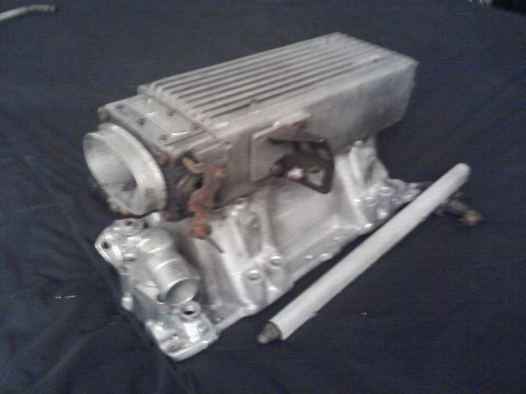
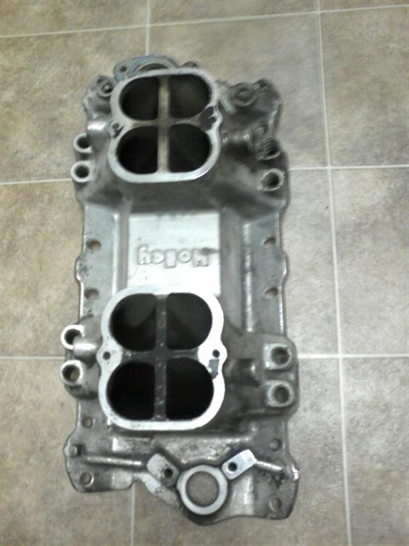
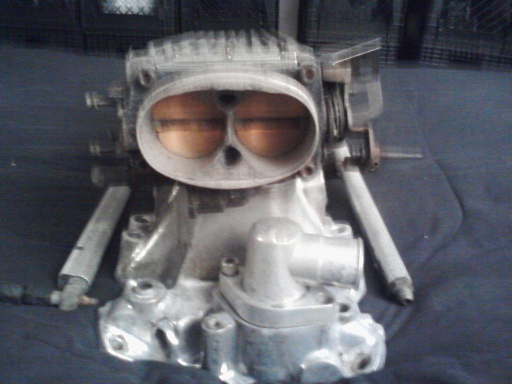
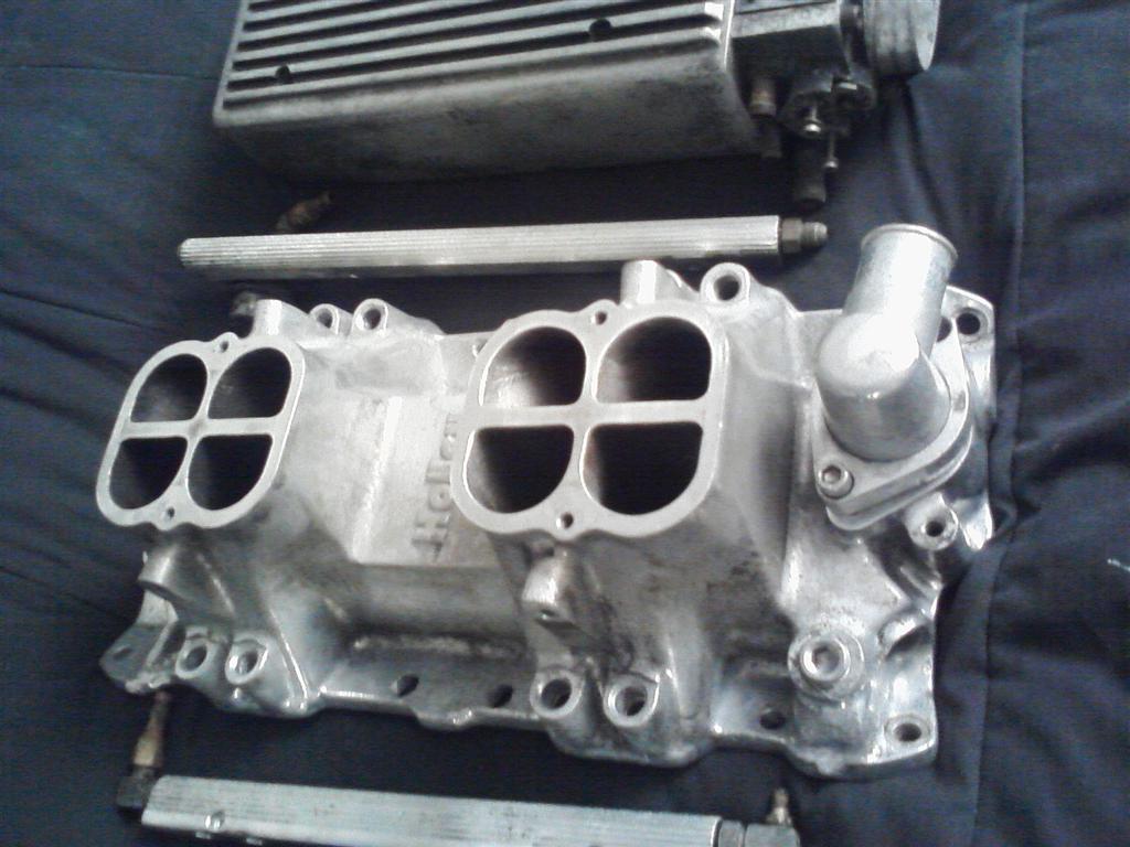
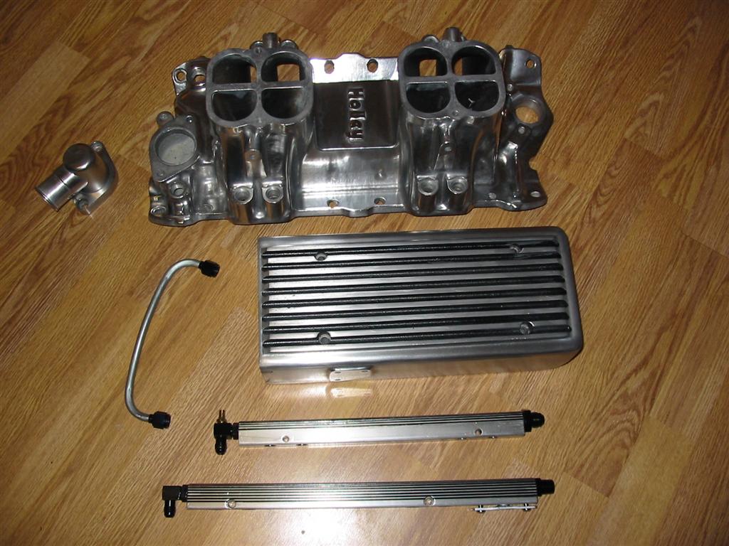
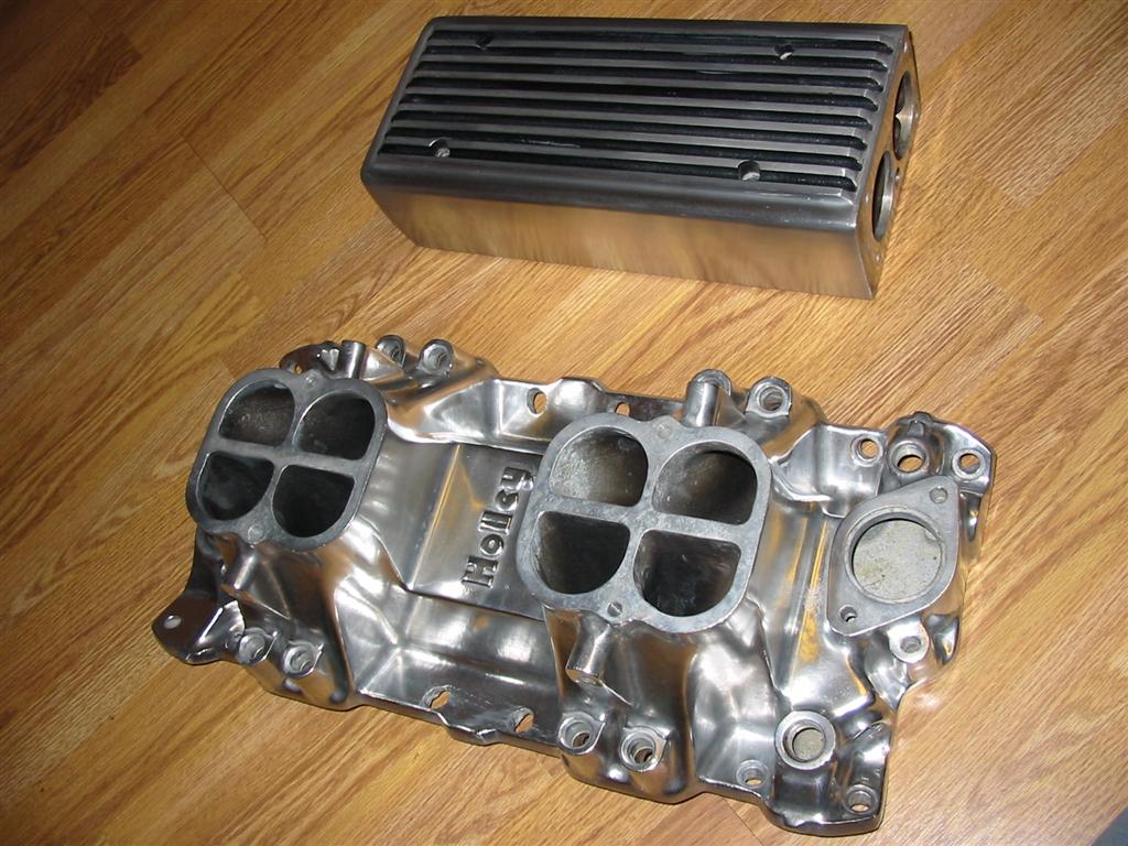
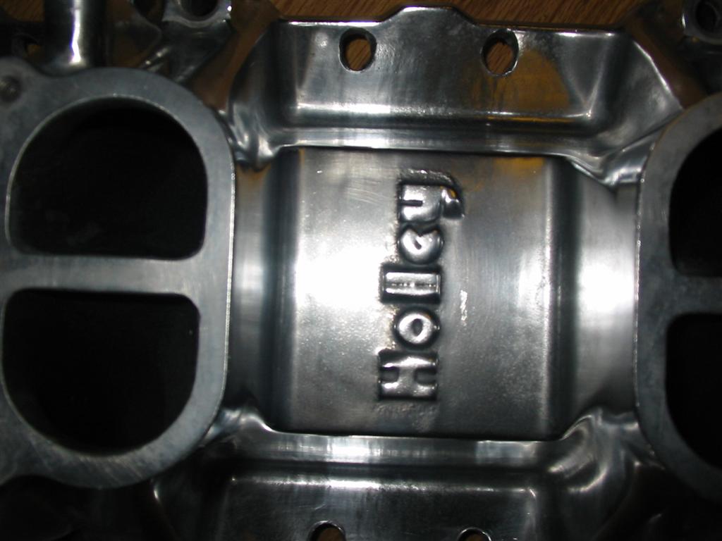
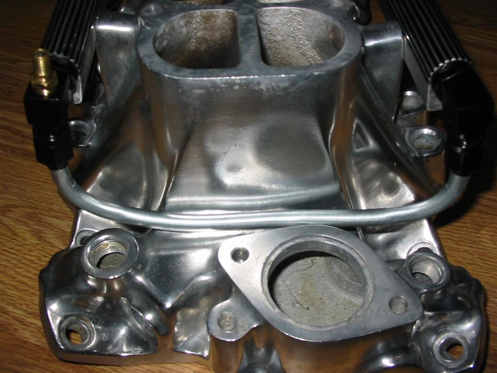
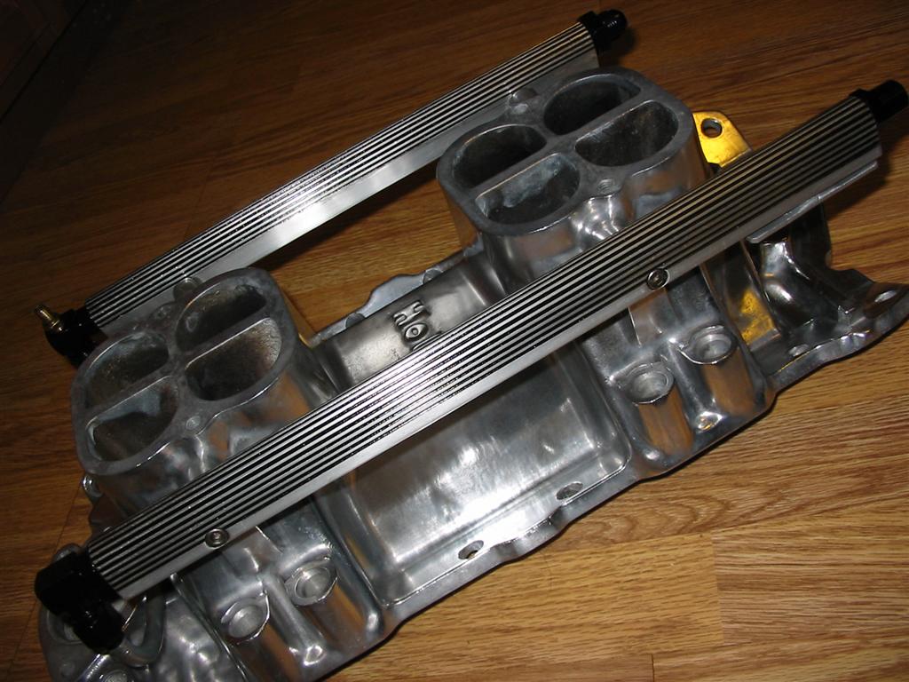
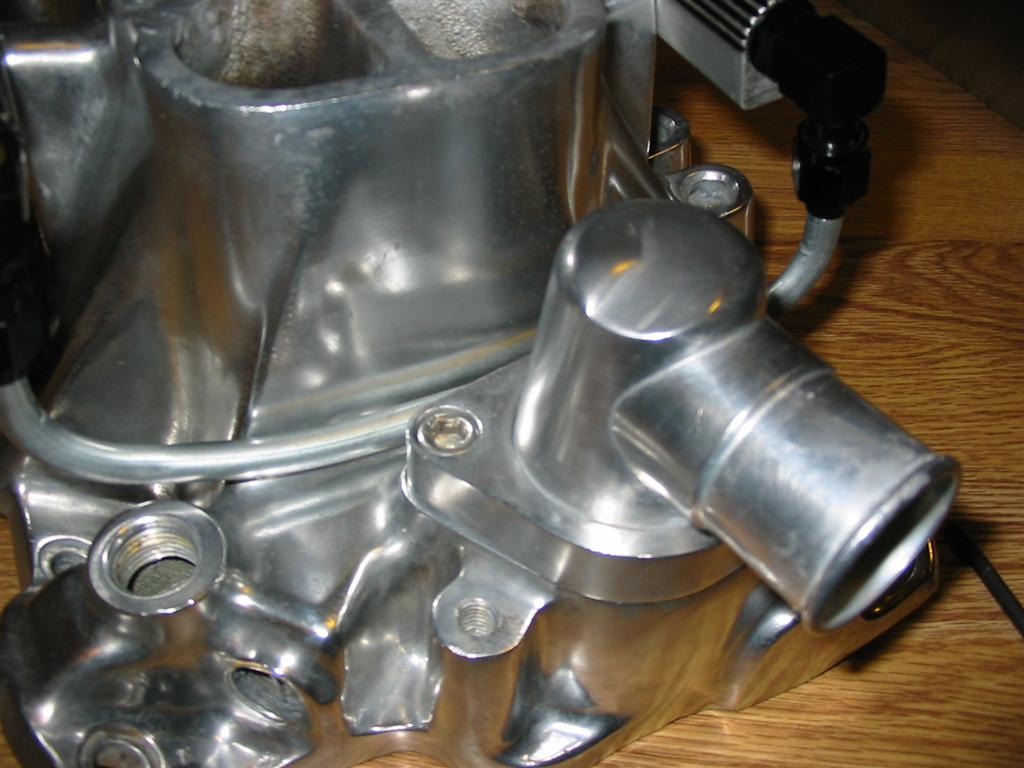
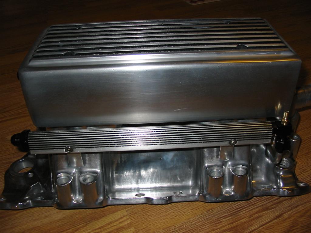
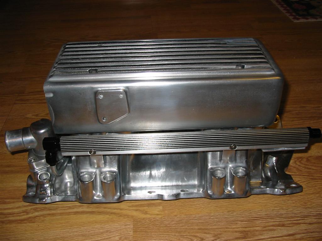
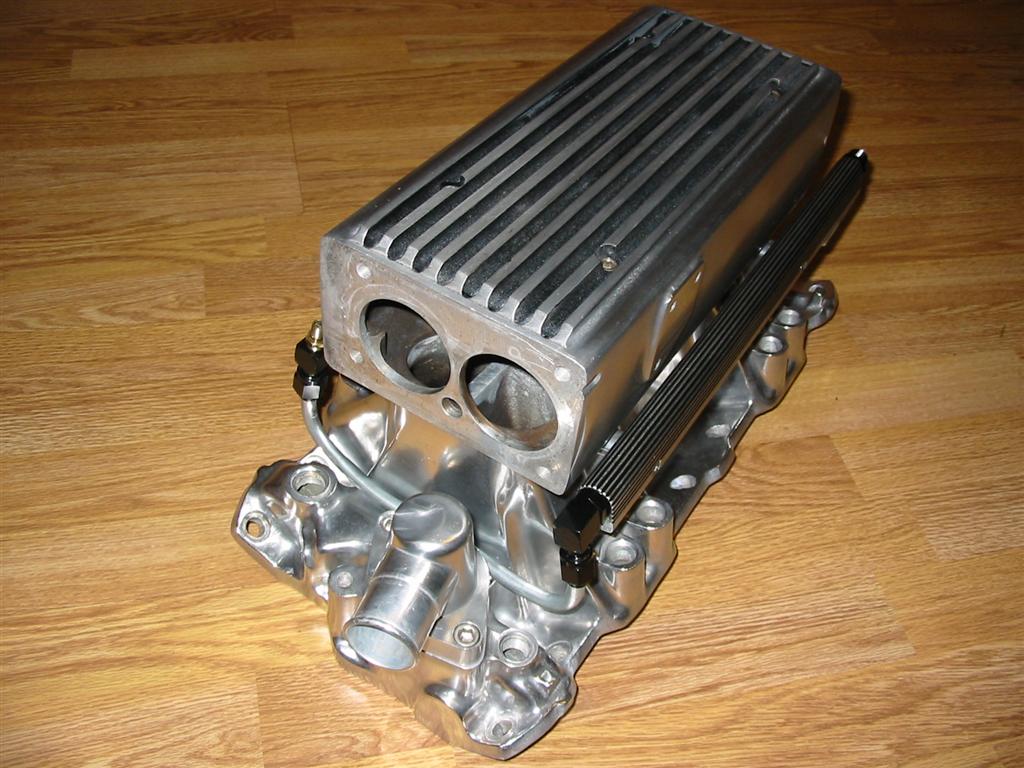
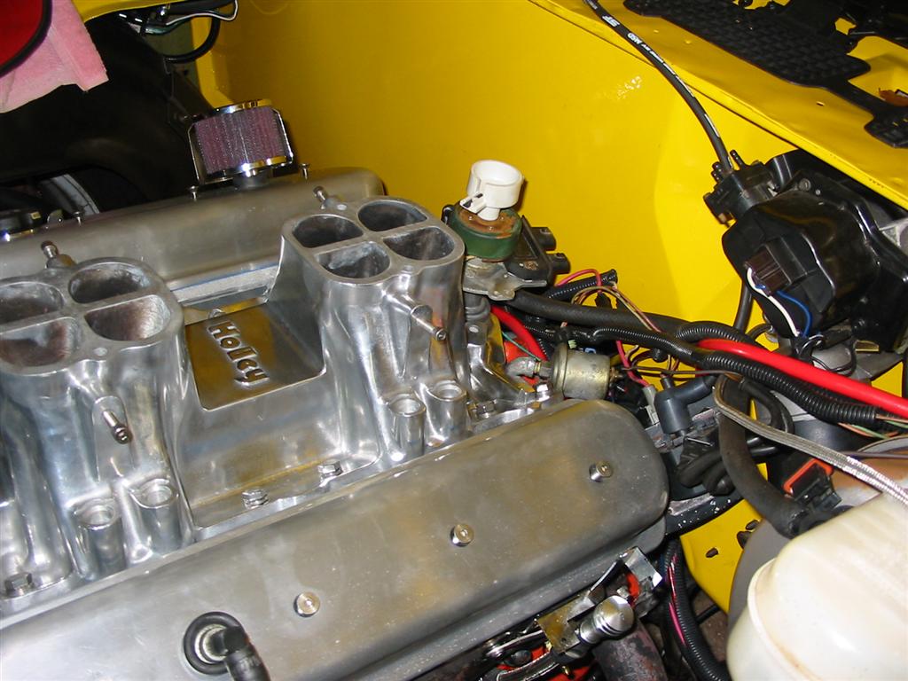
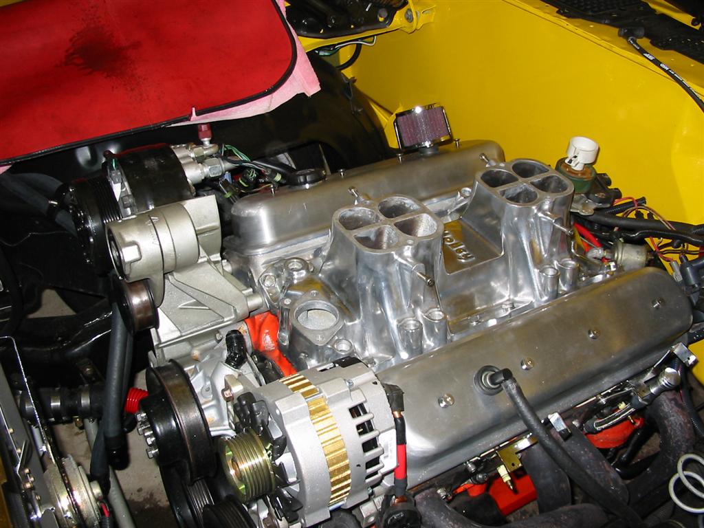
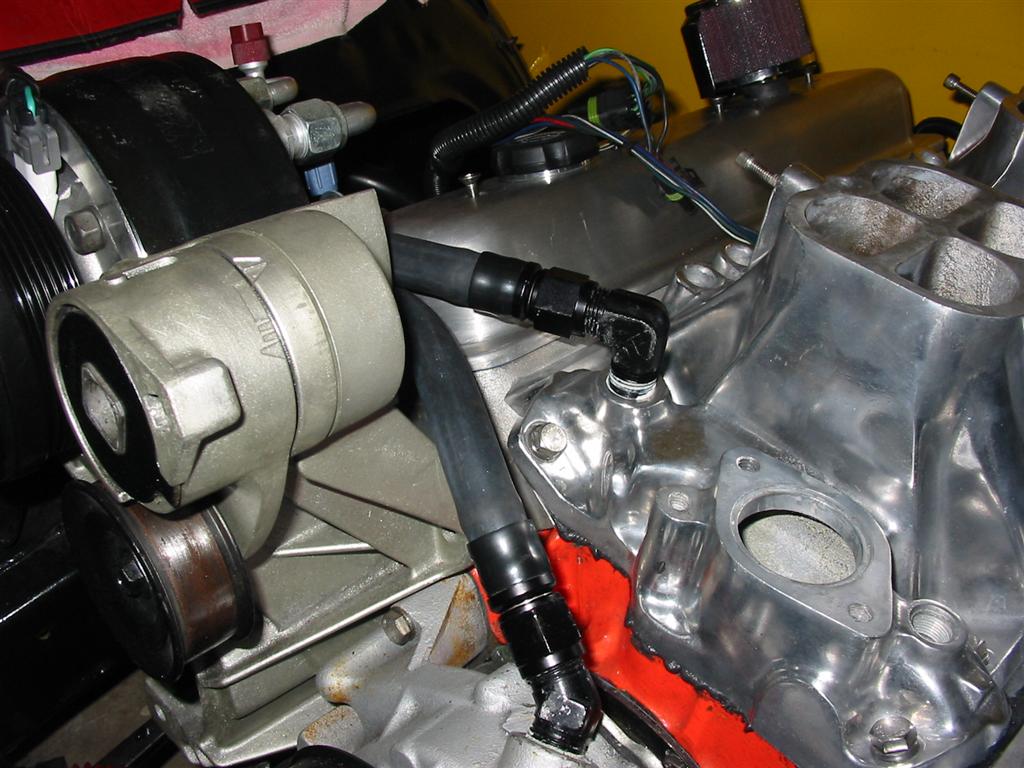
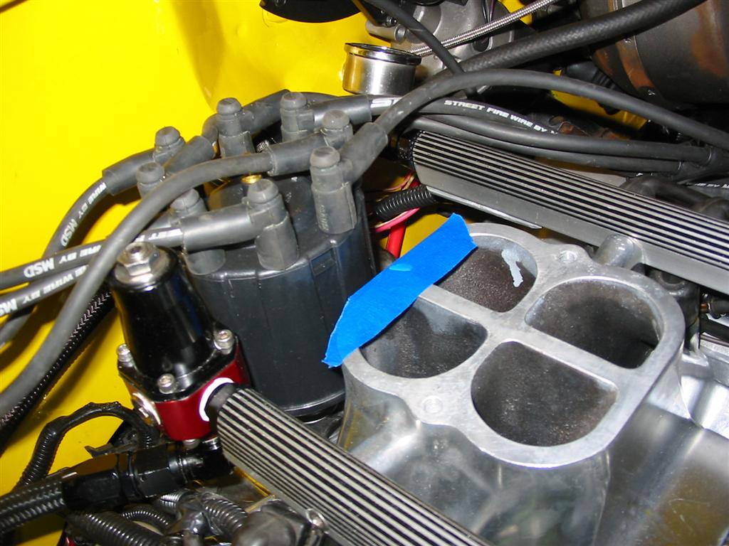
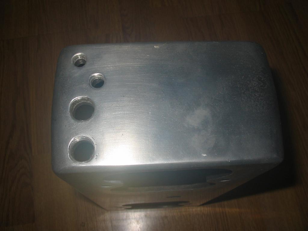
| Here pictures of the intake before I got it. I didn't get the throttle body in the sale. | |
|
|
|
|
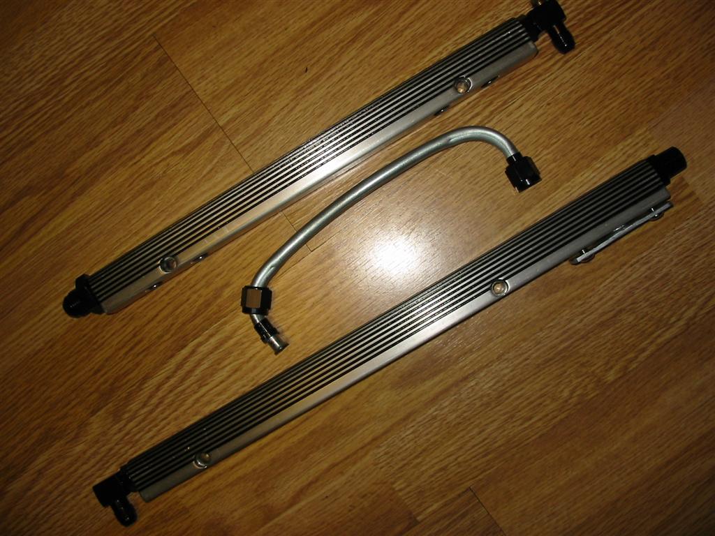
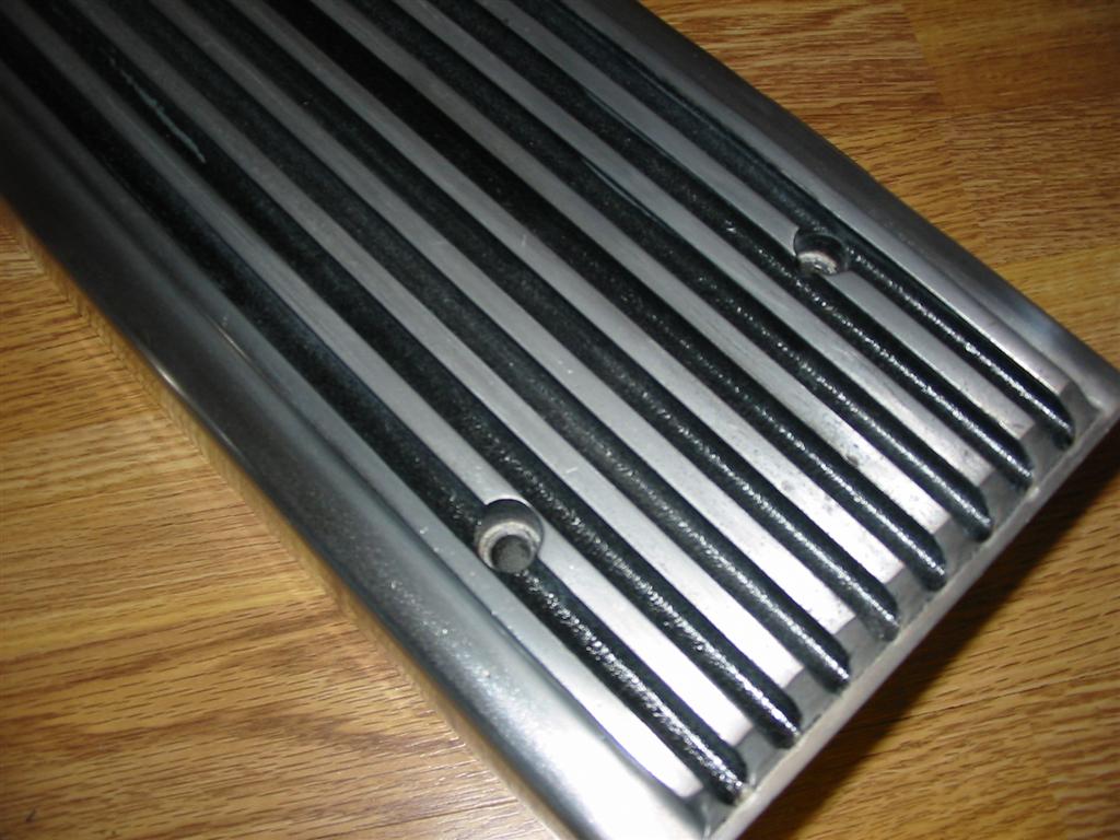
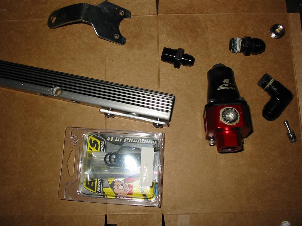
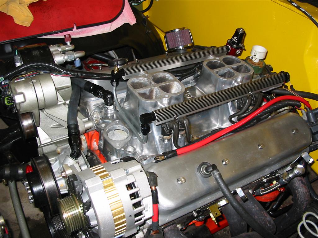
| The following pictures are of the intake and fuel rails after a thorough cleaning and polishing. I also painted the groves in the plenum black and the grooves in the fuel rails black. I also needed to create a fuel crossover tube since the original one was gone. I made that out of 3/8 fuel line and AN fittings. I also painted all the fuel rail fittings black. | |
|
|
|
|
|
|
|
|
|
|
|
|
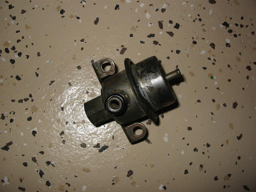
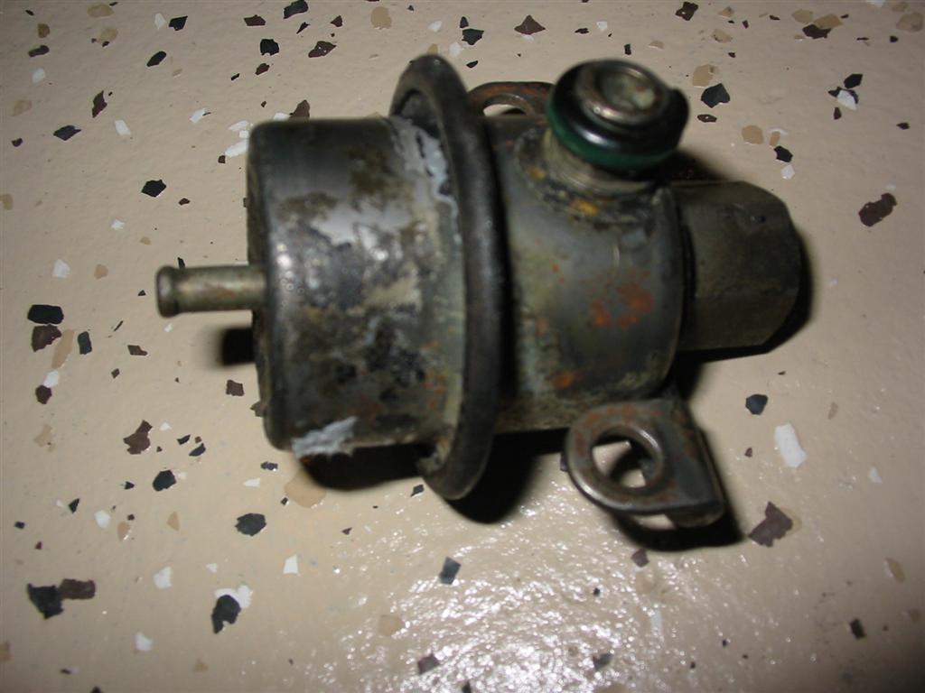
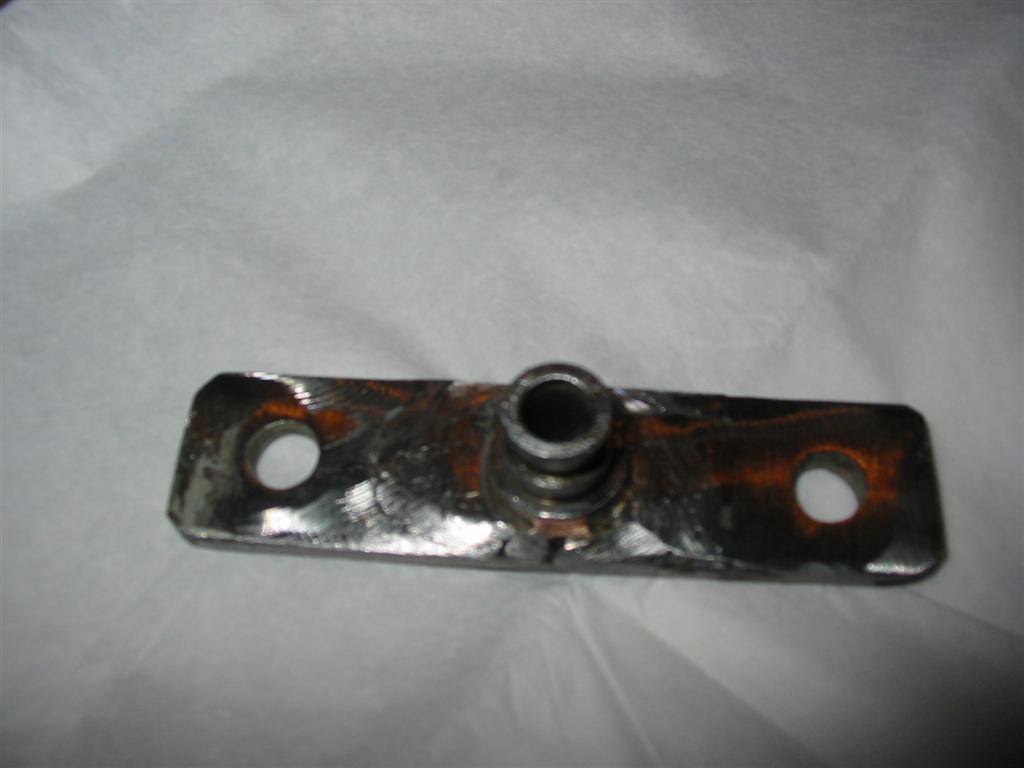
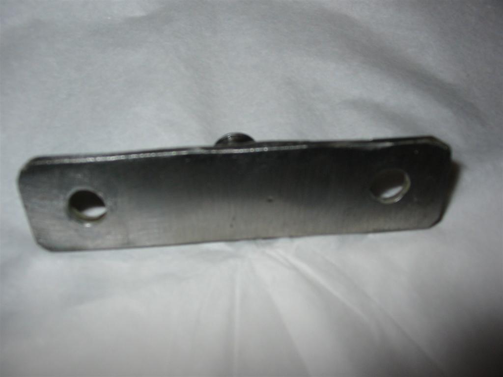
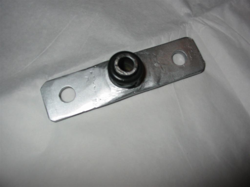
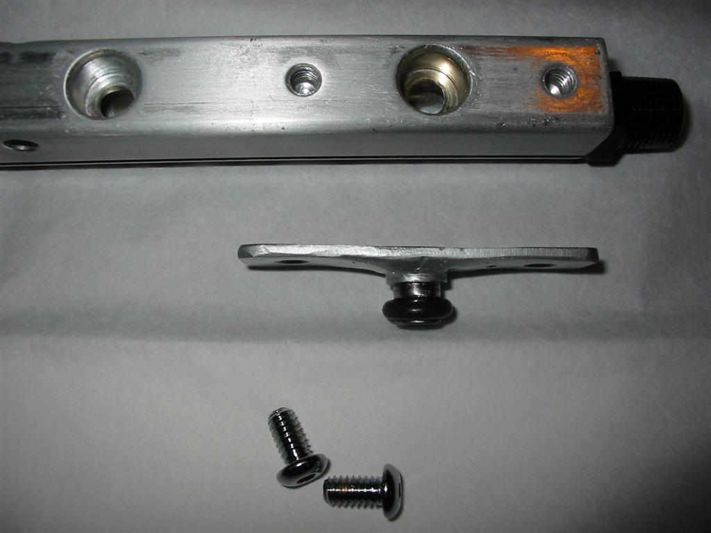
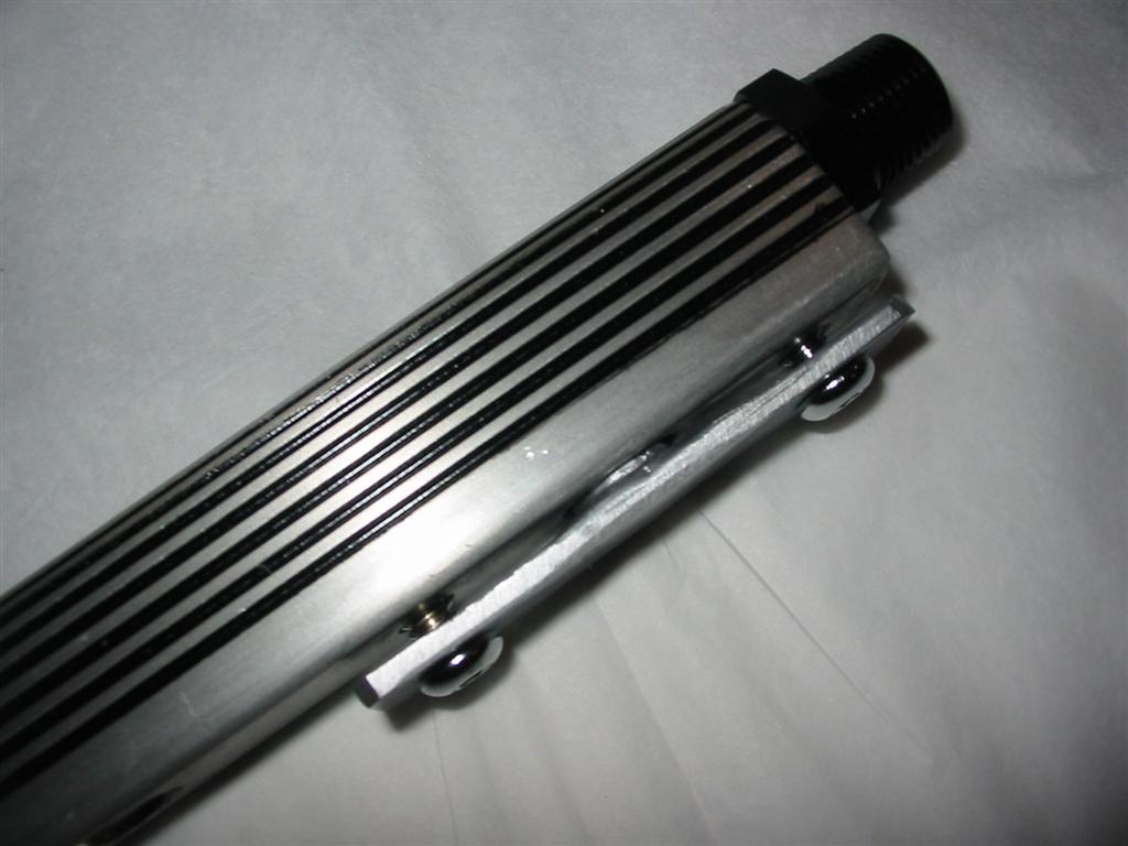
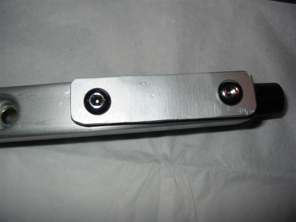
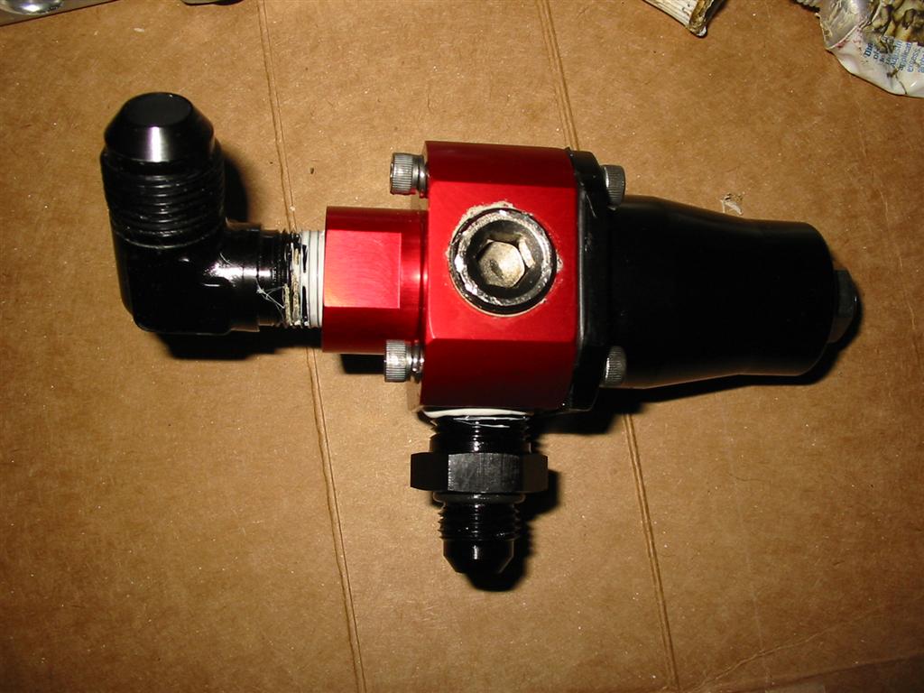
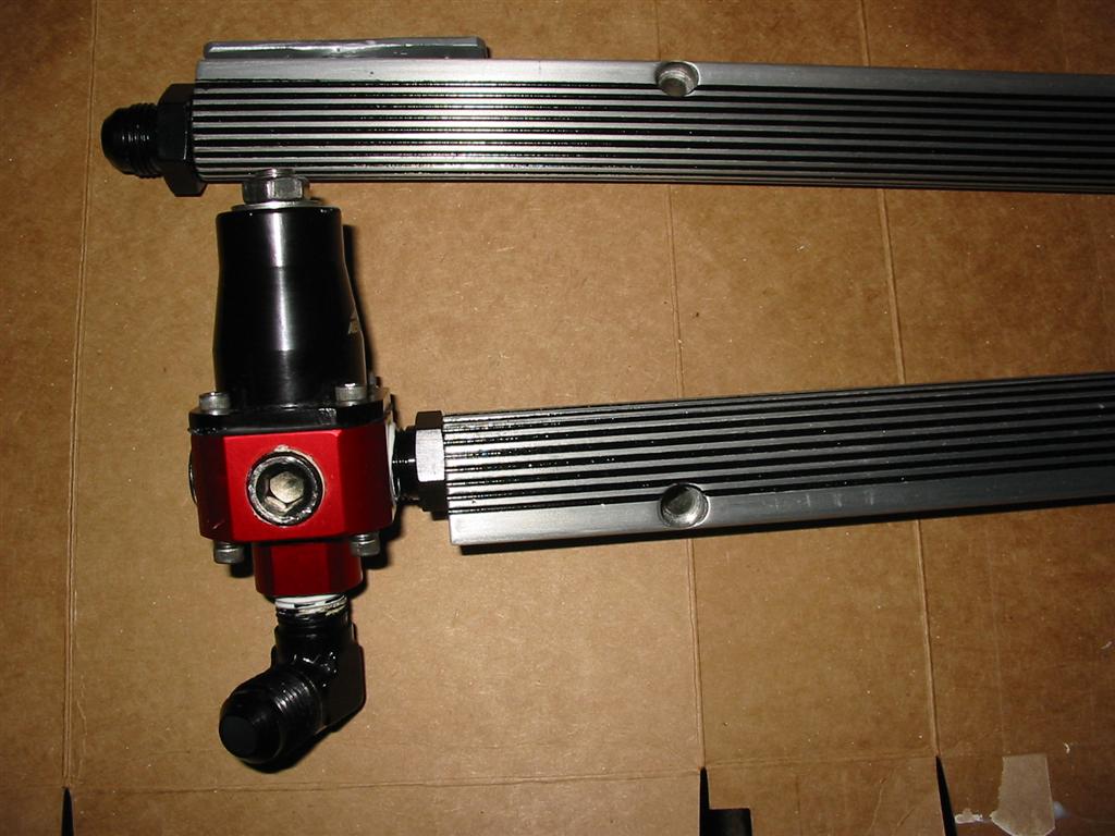
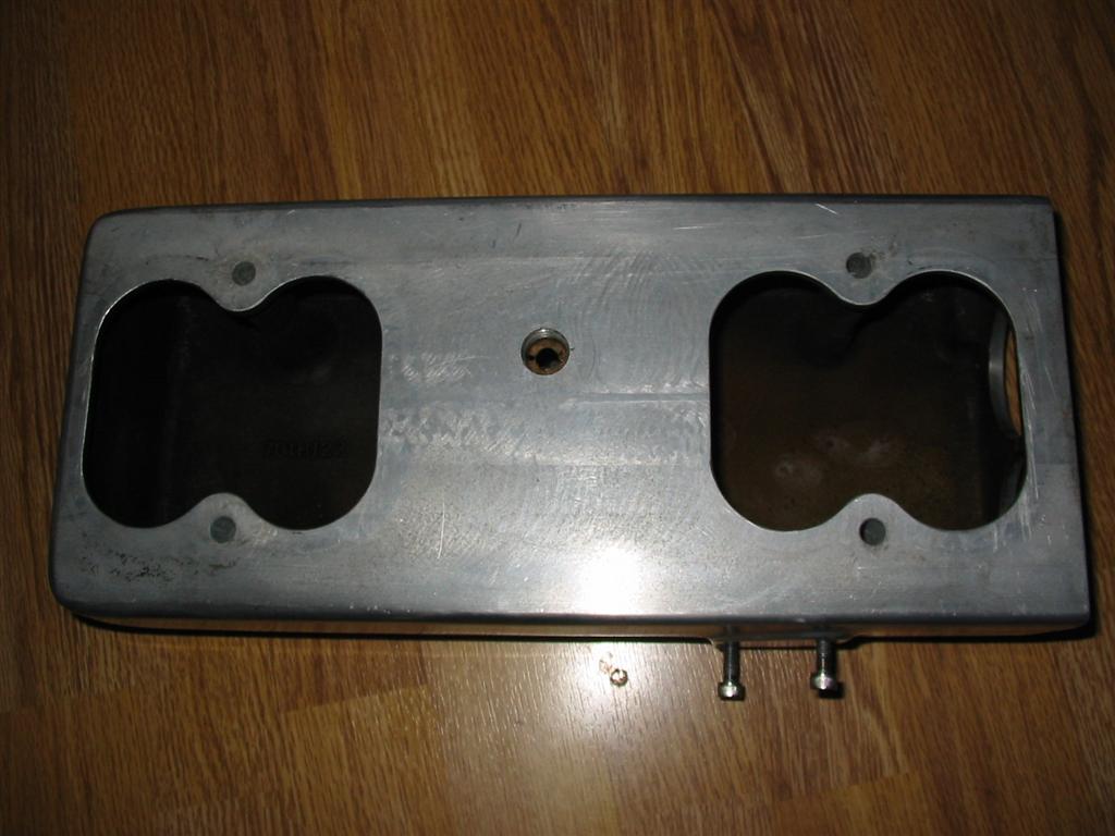
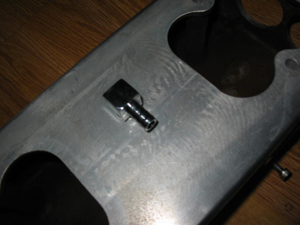
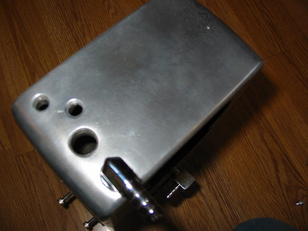
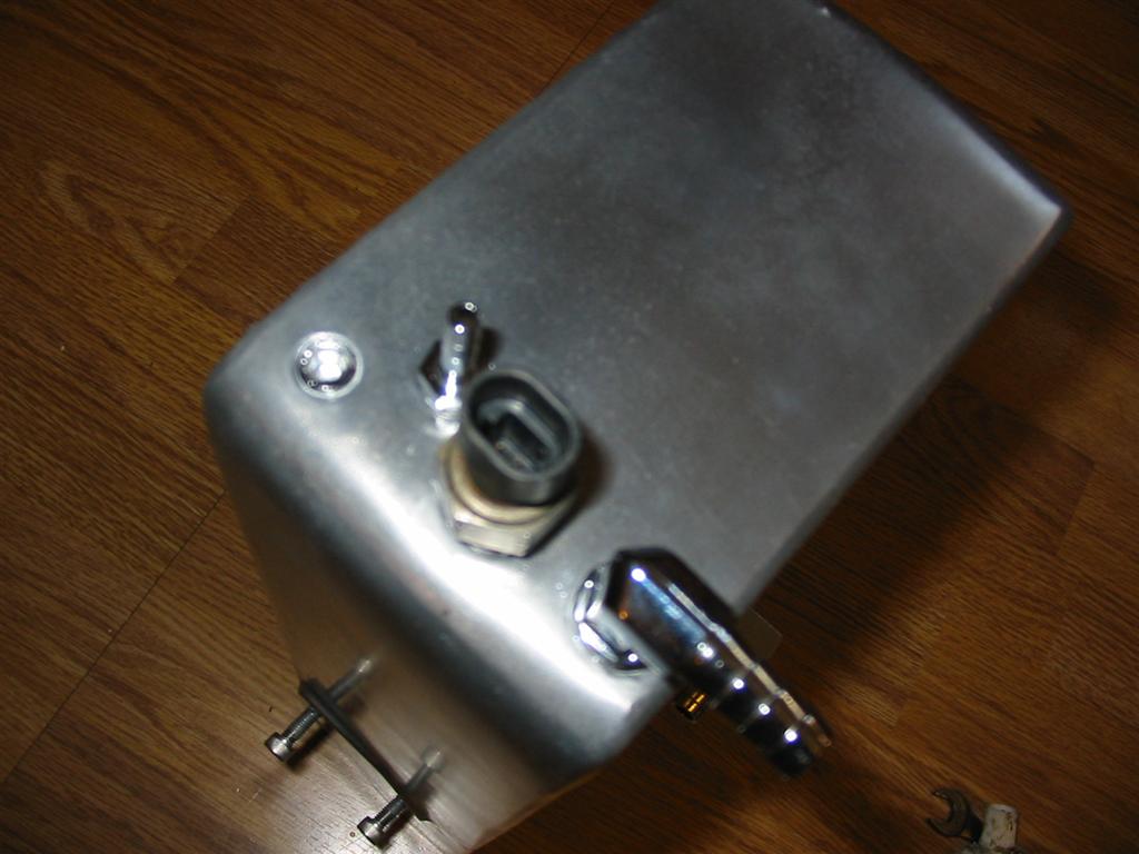
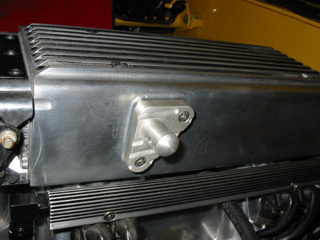
| Here are pictures of the factory Holley regulator. This was also damaged in the fire but, that didn't concern me because I already had an Aeromotive adjustable regulator. The only issue is I needed to plug the hole in the fuel rail where the regulator mounts and use the rear rail fittings for the fuel lines. I cut up the old regulator to get the nipple that goes into the fuel rail. I then welded this nipple to a solid piece of steel. This was then bolted to the fuel rail. | |
|
|
|
|
|
|
|
|
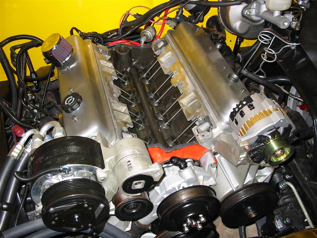
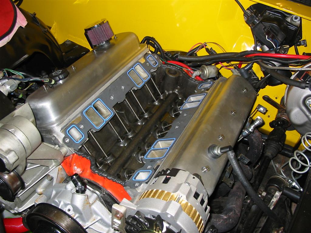
| First I needed to remove the TPI intake manifold from the engine. | |
|
|
|
|
|
|
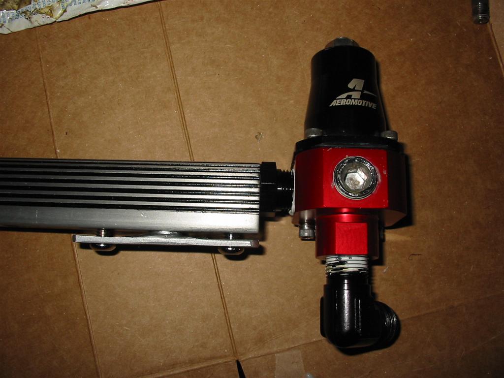
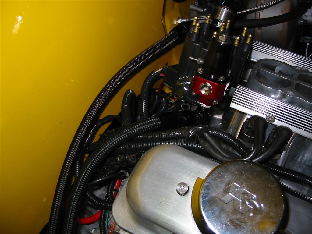
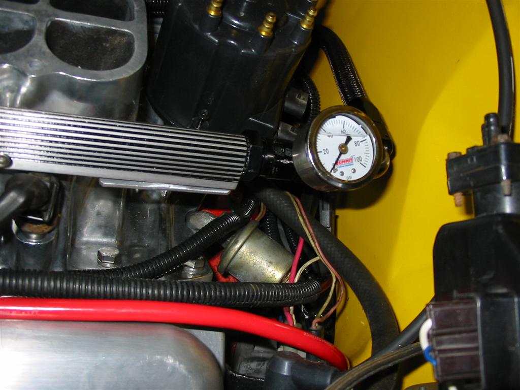
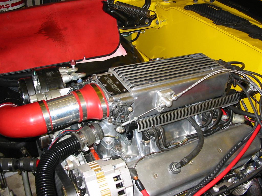
| I then mounted the Aeromotive regulator to the fuel rail. Originally I had it install on passenger side but moved it to the driver's side for clearance reasons. | |
|
|
|
|
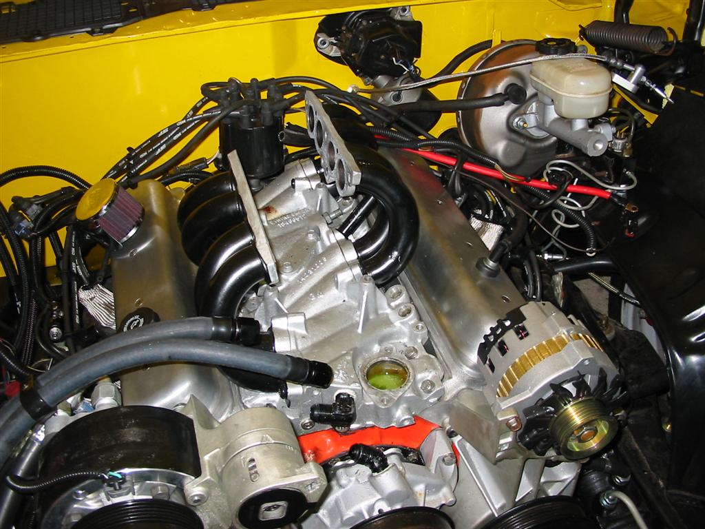
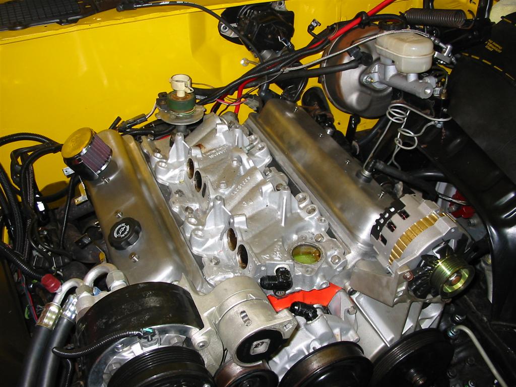
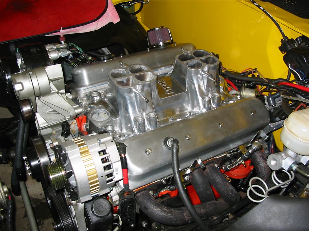
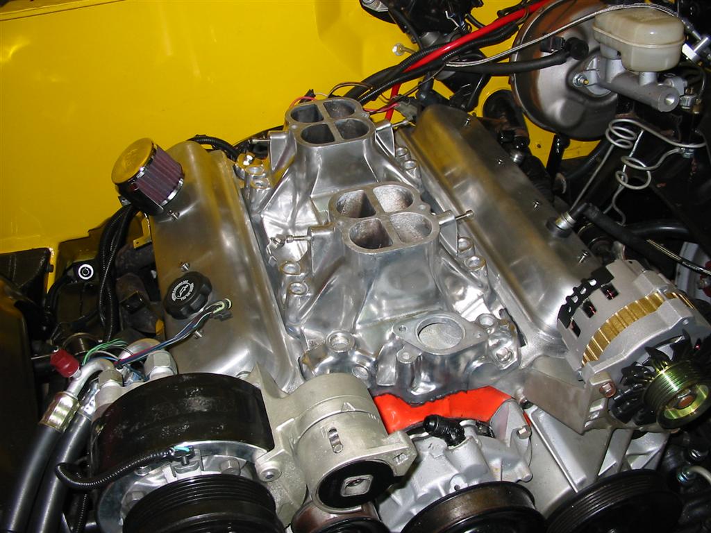
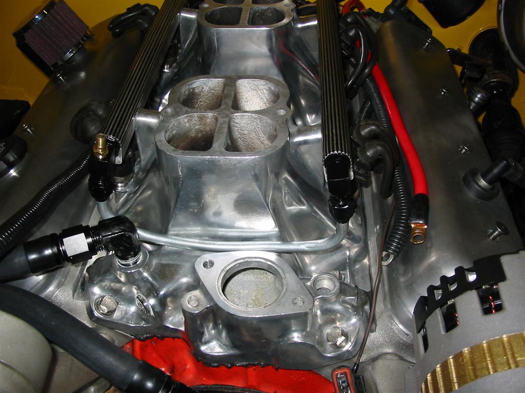
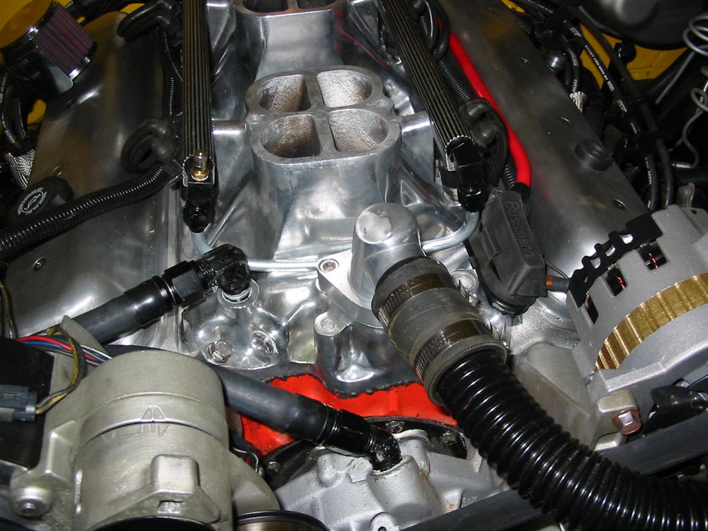
| The next step was to install the lower portion of the intake. | |
|
|
|
|
|
|
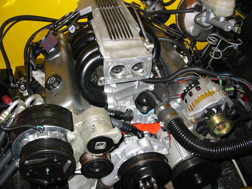
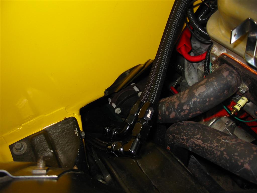
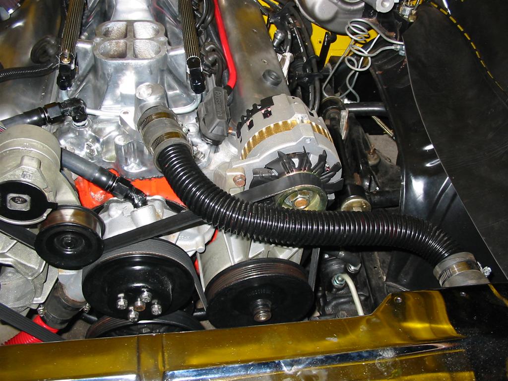
| Next was the various plumbing. I hooked up the heater lines and then installed the fuel rails and injectors. | |
|
|
|
|
|
|
|
|
|
|
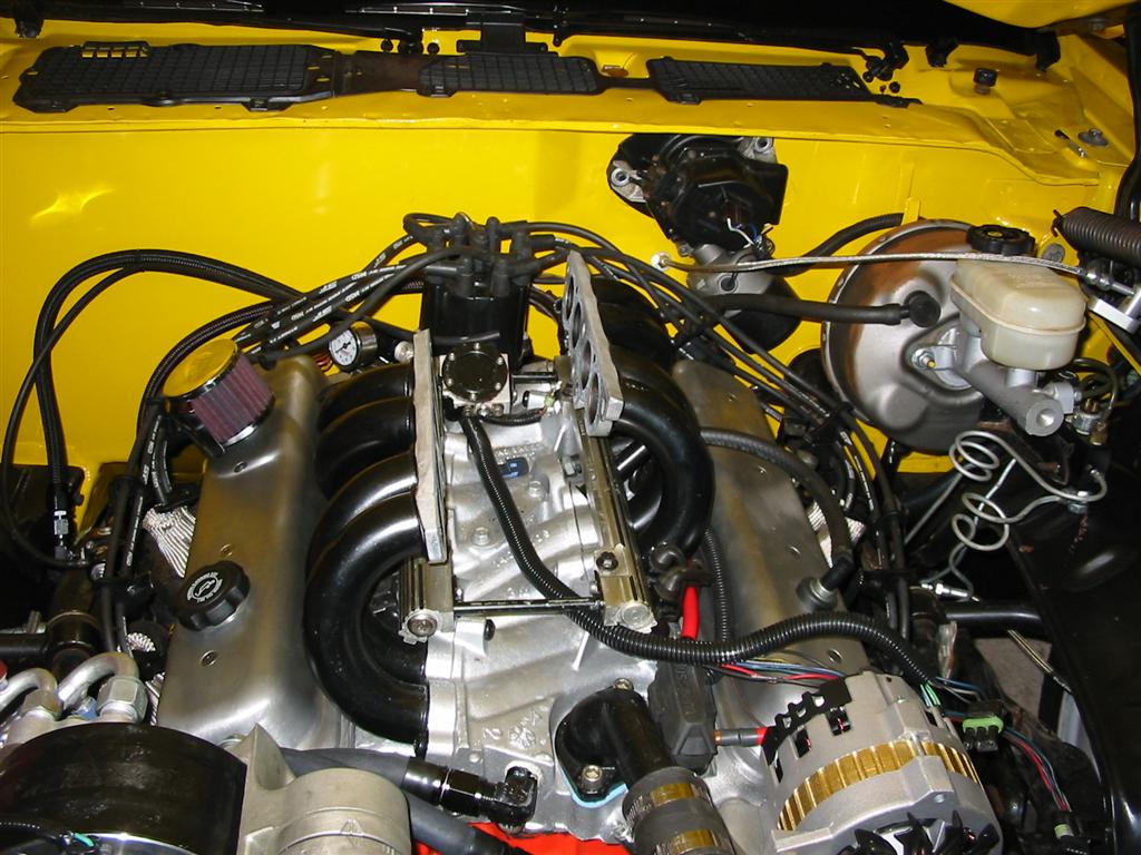
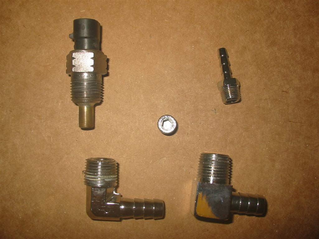
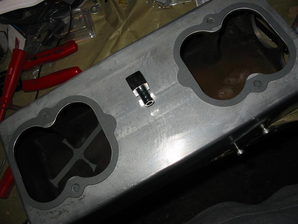
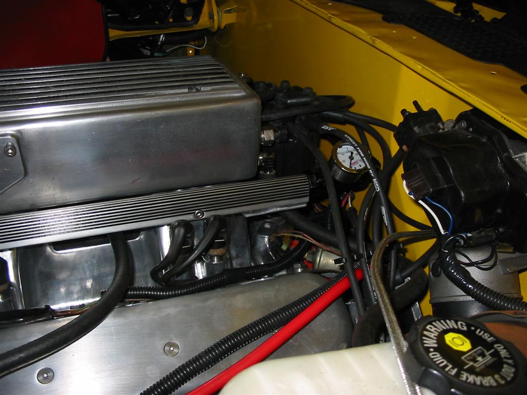
| Next I installed the various vacuum fittings and the intake air temperature sensor into the upper plenum. | |
|
|
|
|
|
|
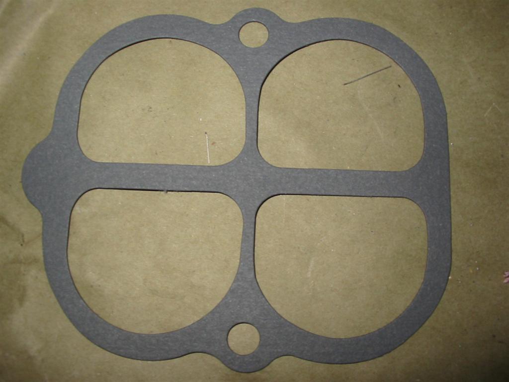
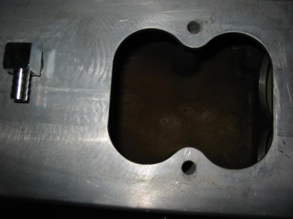
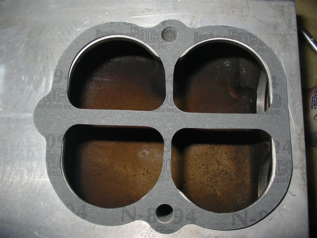
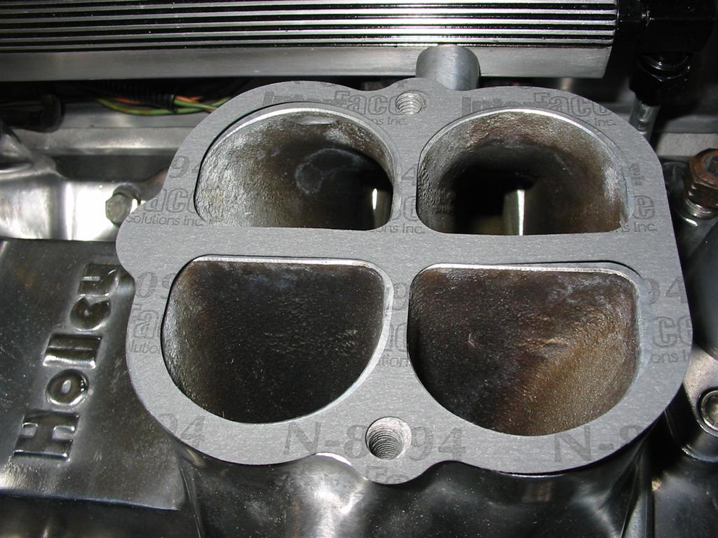
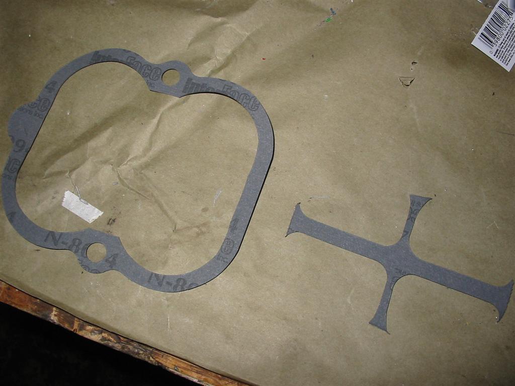
| The next step was to modify the gasket used between the upper and lower plenum. The gasket was originally for a tunnel ram. To make the gasket work I needed to remove the center section in the gasket. | |
|
|
|
|
|
|
| Here is the whole mainshaft now loaded up with the 3rd and 4th gear assemblies and with the input shaft test fitted. | |
|
|
|
|
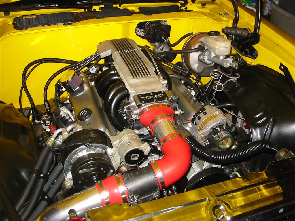
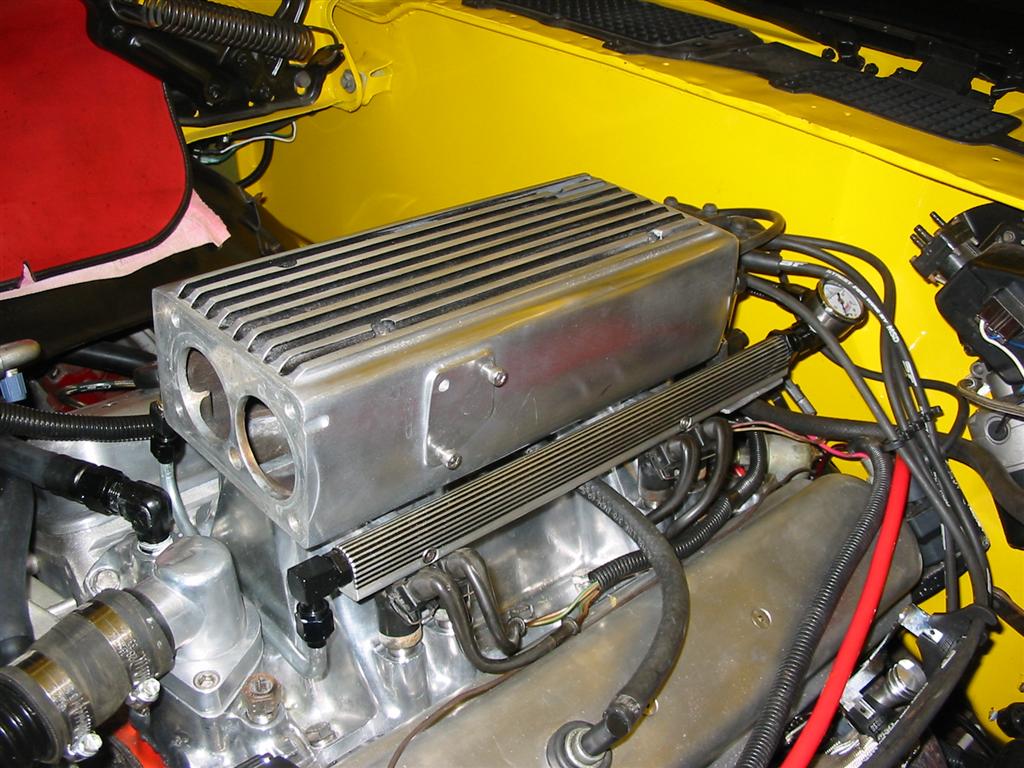
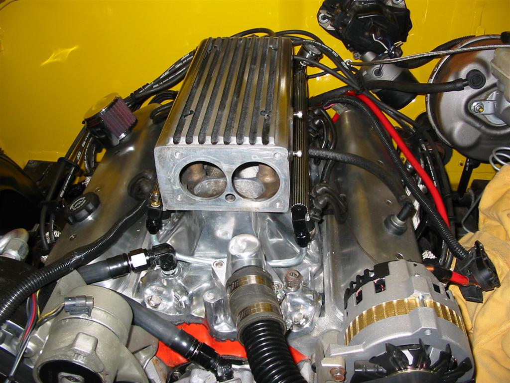
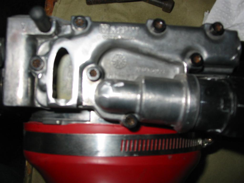
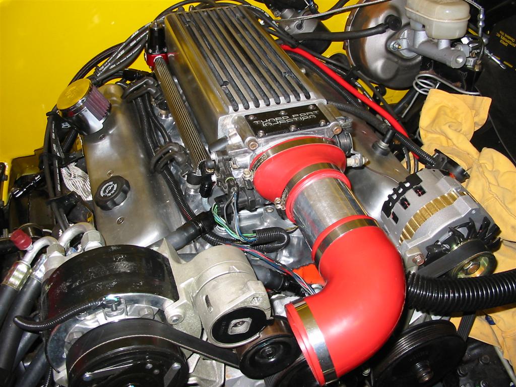
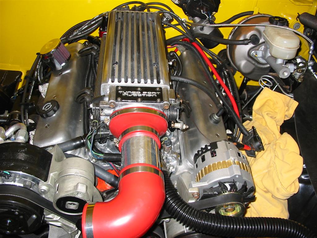
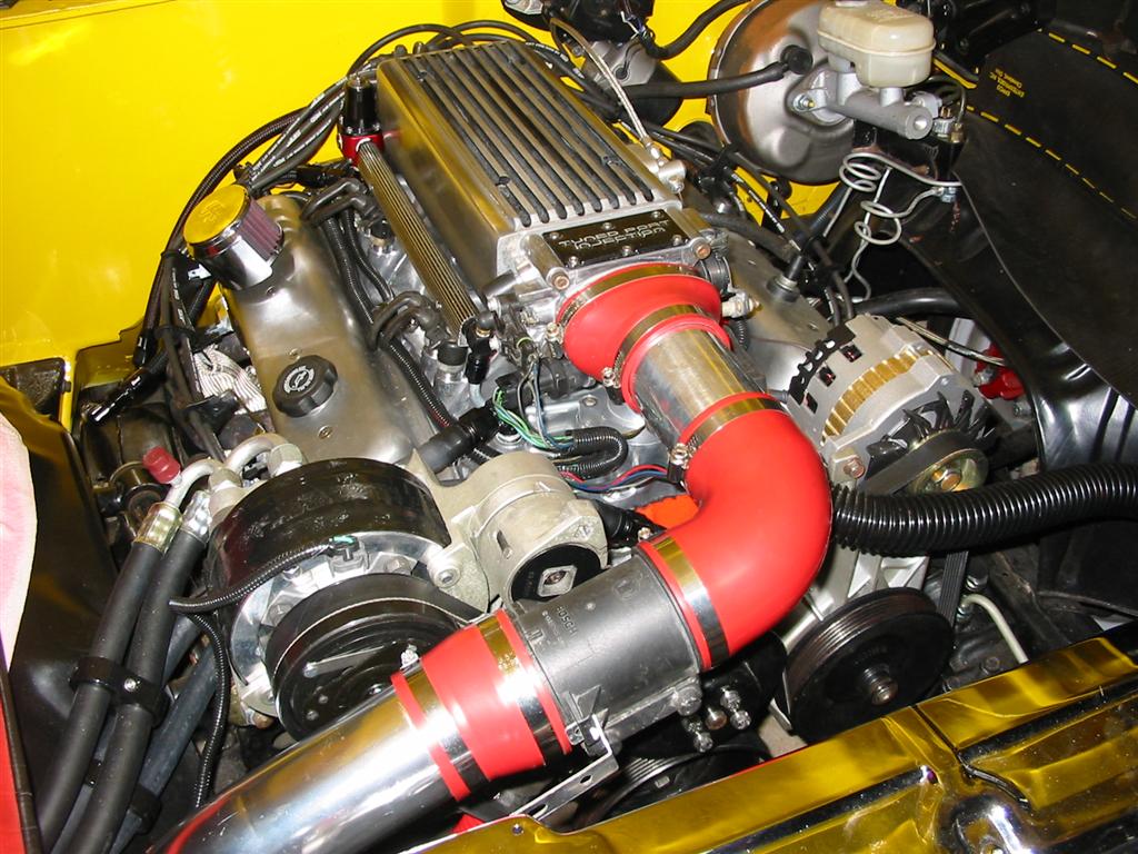
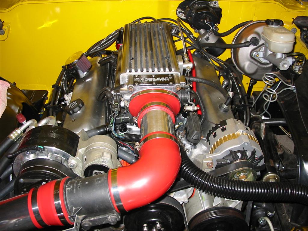
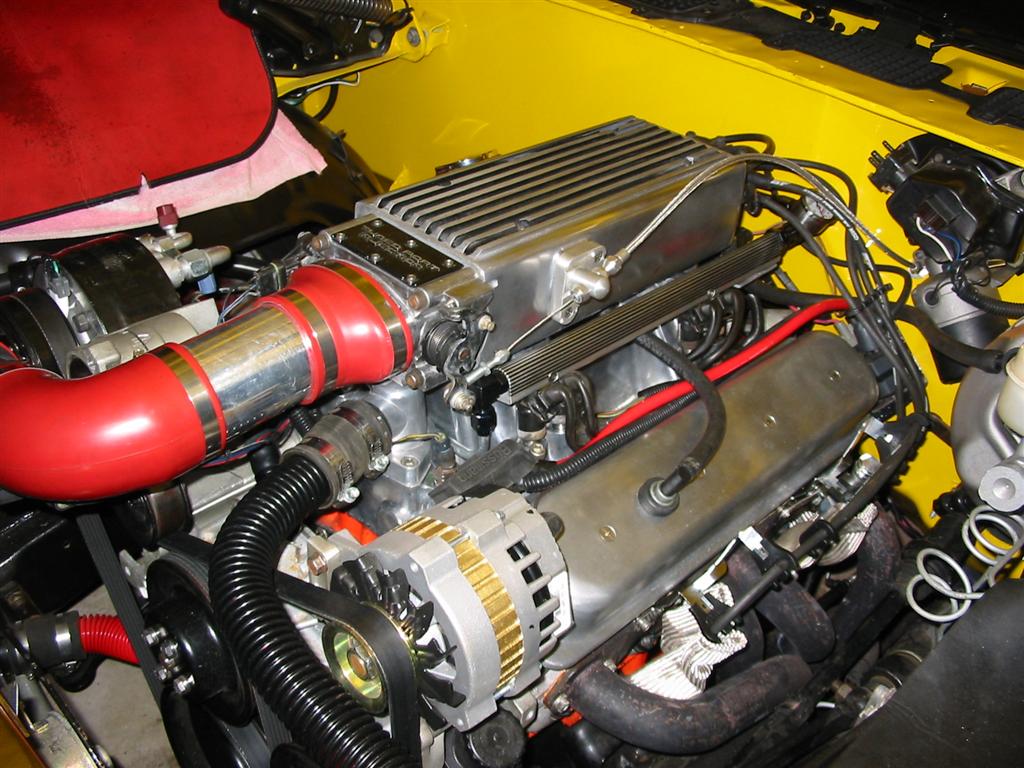
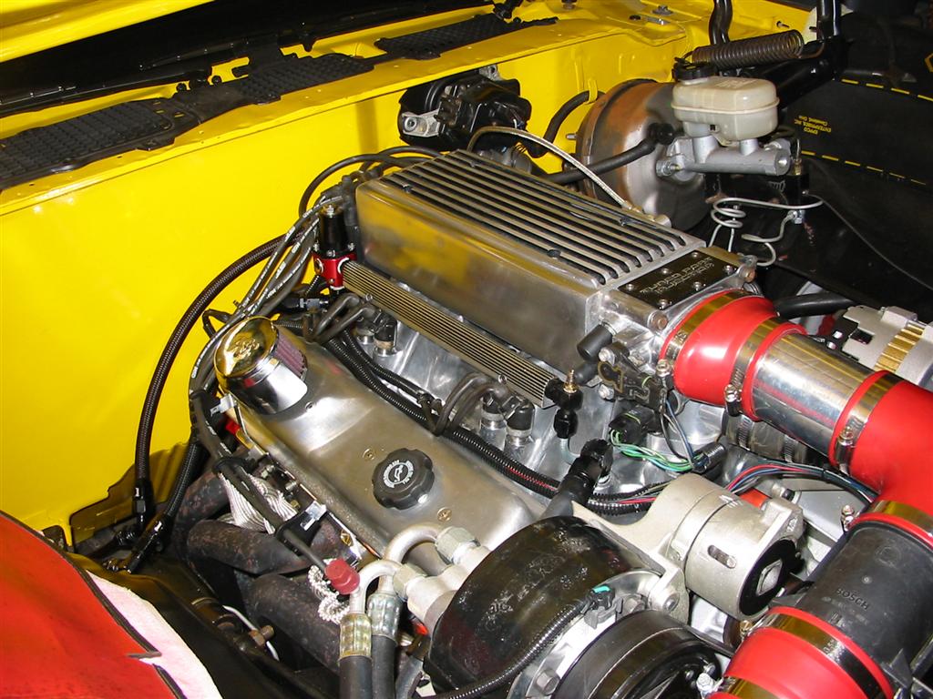
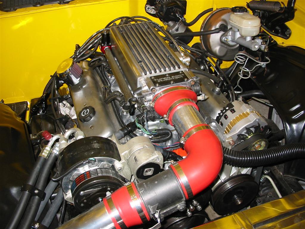
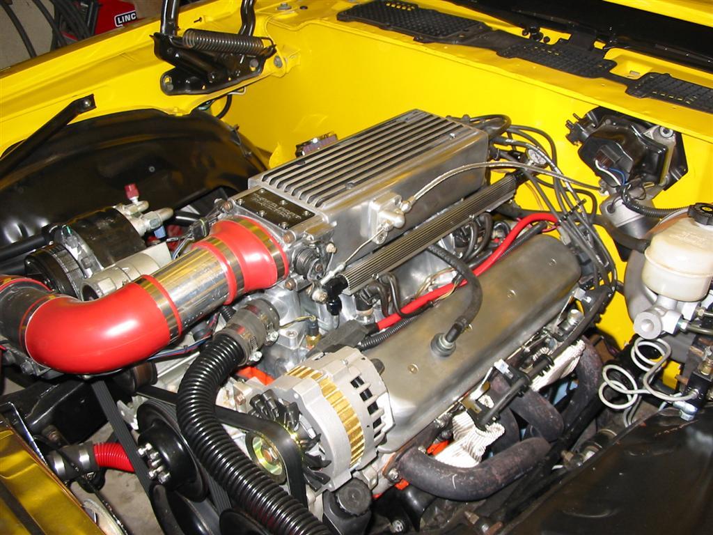
| The bottom of the throttle body required a bit of clearancing to clear the water neck. Lastly, I then installed the throttle body, intake tract with MAF sensor, Lokar throttle bracket, and wiring. | |
|
|
|
|
|
|
|
|
|
|
|
|