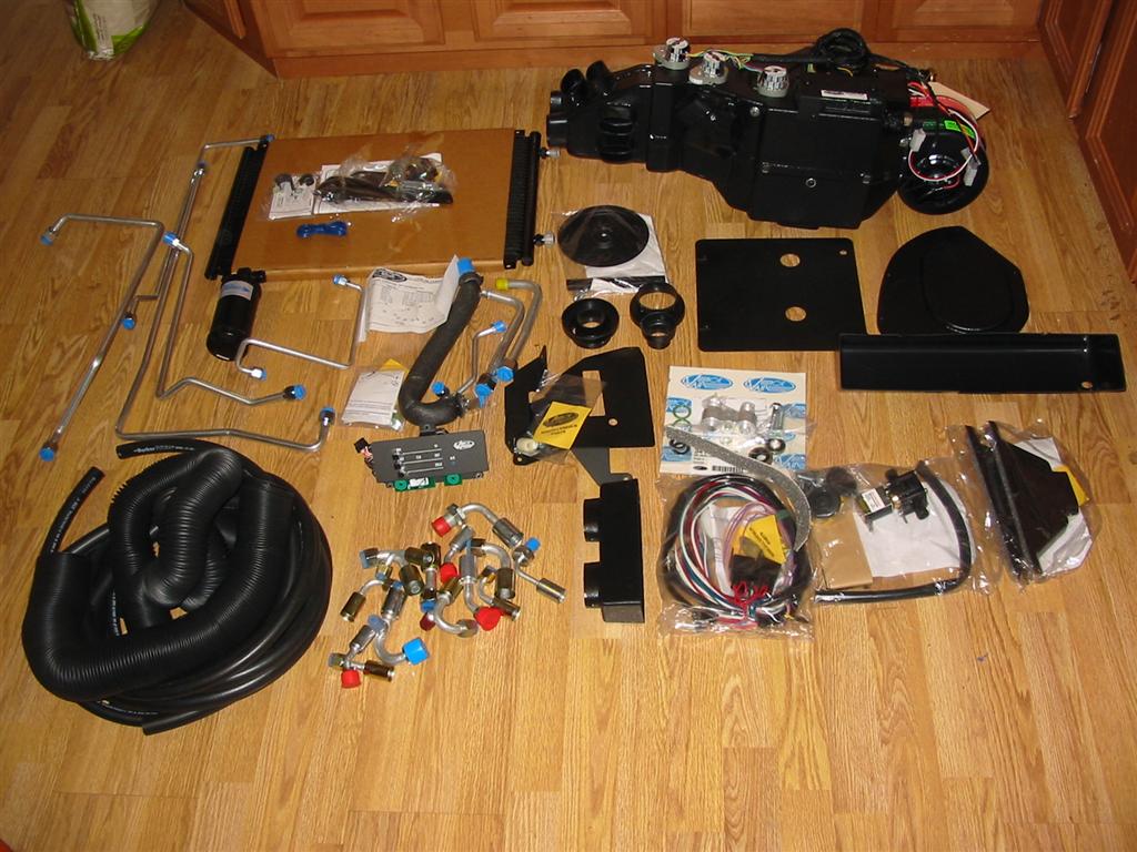
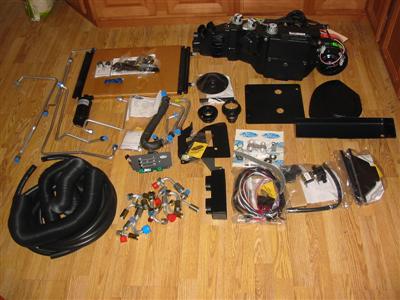
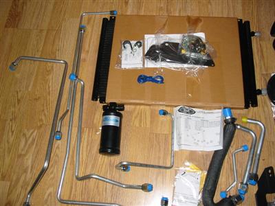
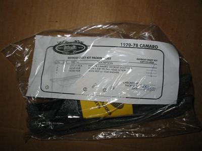
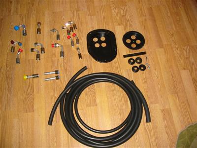
| Here are pictures everything that comes in the standard Sure Fit system and some of
the hidden hose options. Due to issues with Vintage Air some of the hidden hose
parts were missing. The parts not shown are the kick panel, special fan hole
block off for the firewall and a few heater hose fittings. |
|
|
|
|
|
|
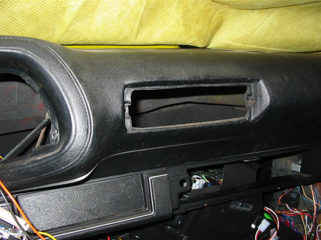
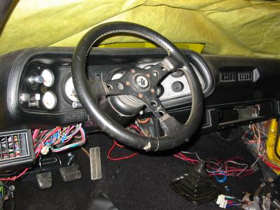
| The first step was to remove the console and most of the lower dash pieces. I
also removed the seats because it is much easier to work on this type of
stuff when the seats are not in the way. |
|
|
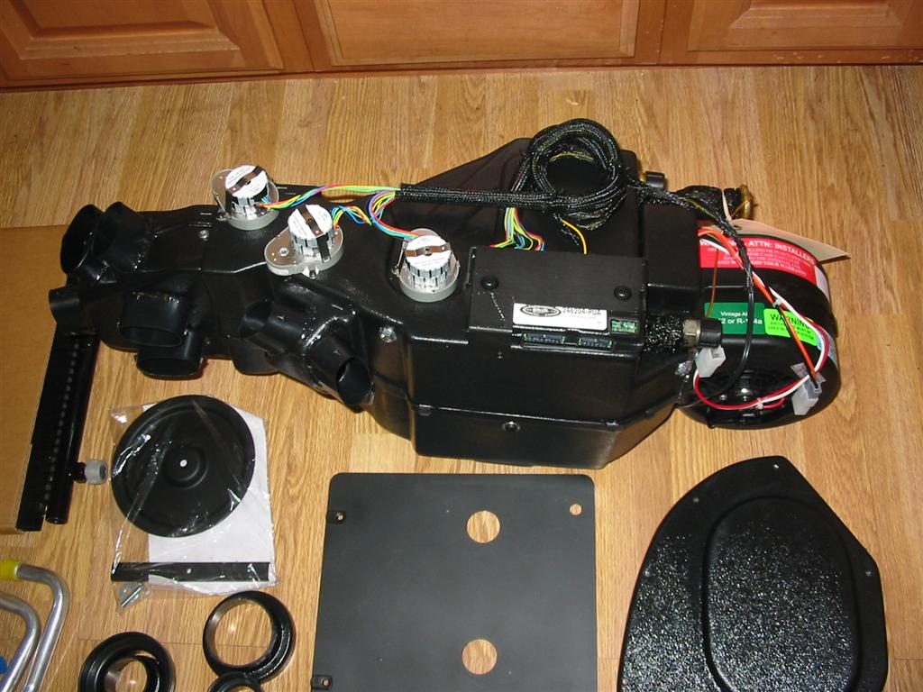
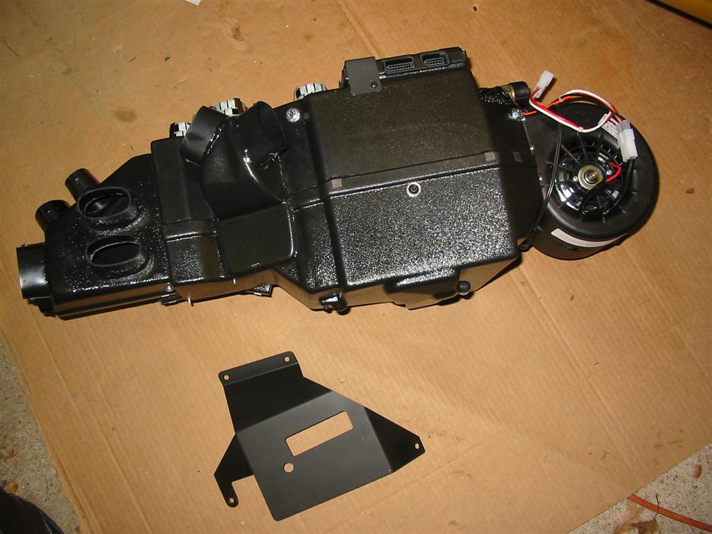
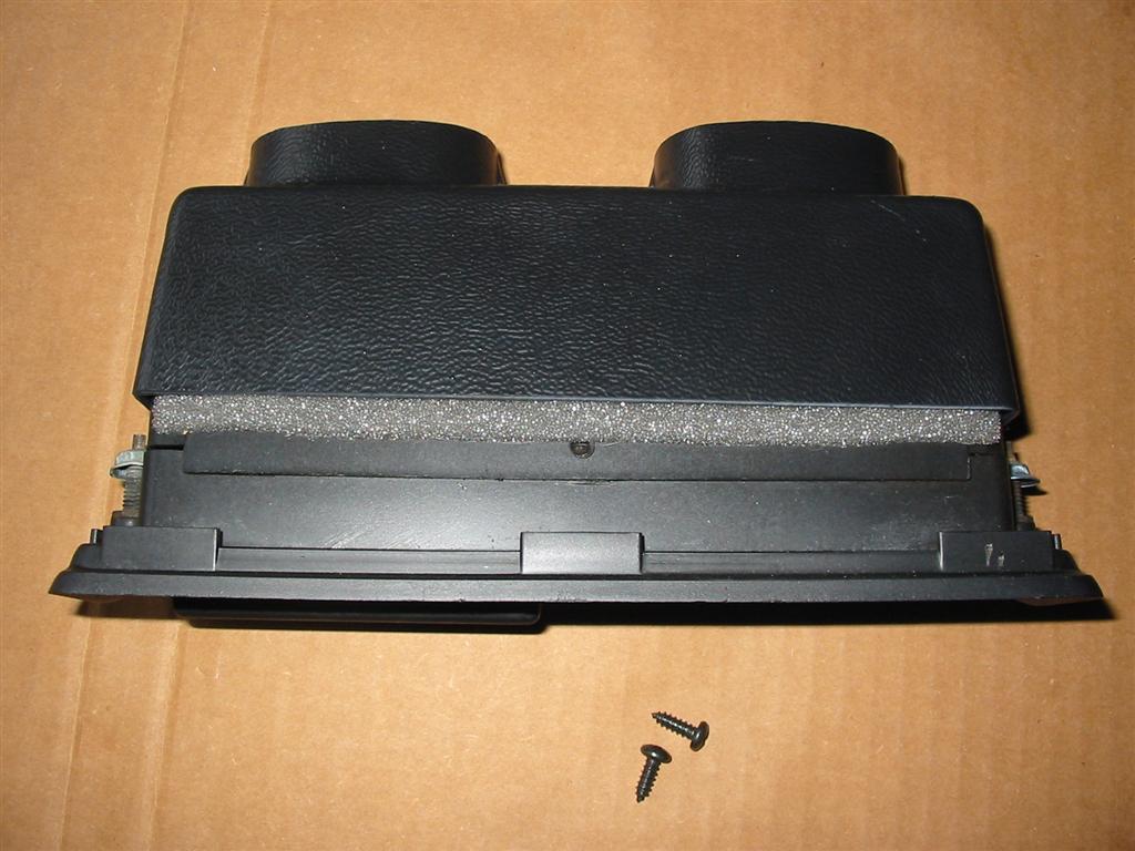
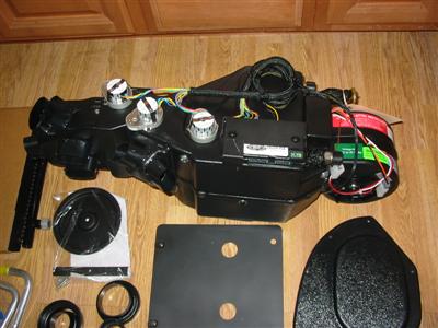
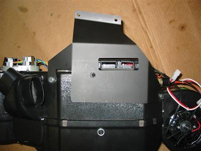
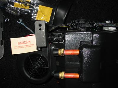
| The heart of the system is the evaporator system that mounts under the dash.
This unit replaces the big ugly box that used to be mounted to the firewall
under the hood and it replaces the distribution box that used to be under
the dash. This unit is all electric and requires no vacuum to run. The
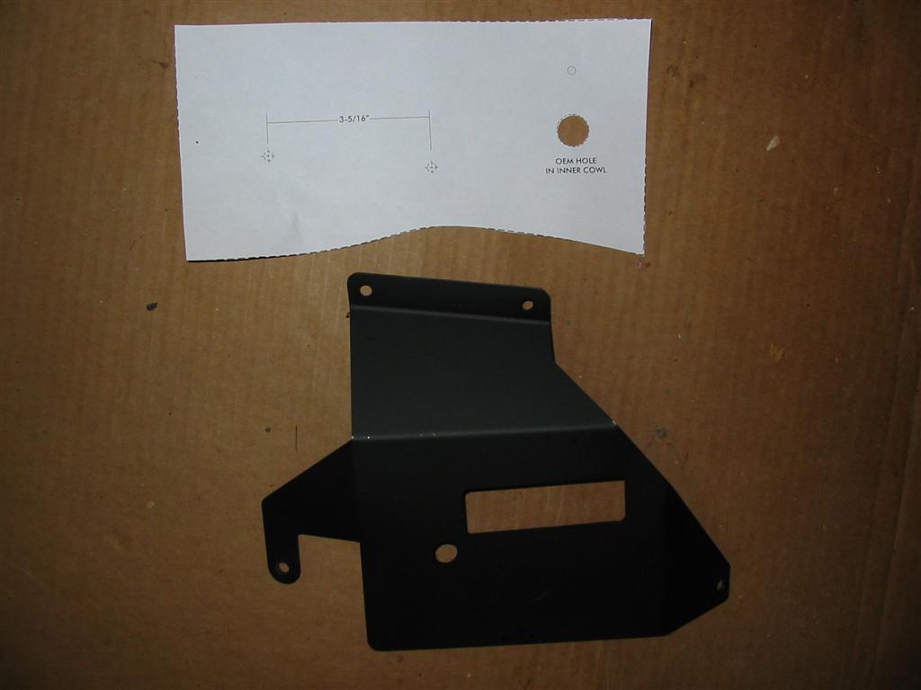
kit comes with a template to mark the holes to be drilled for the upper
mount. |

|

|
|
|
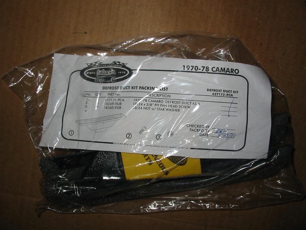
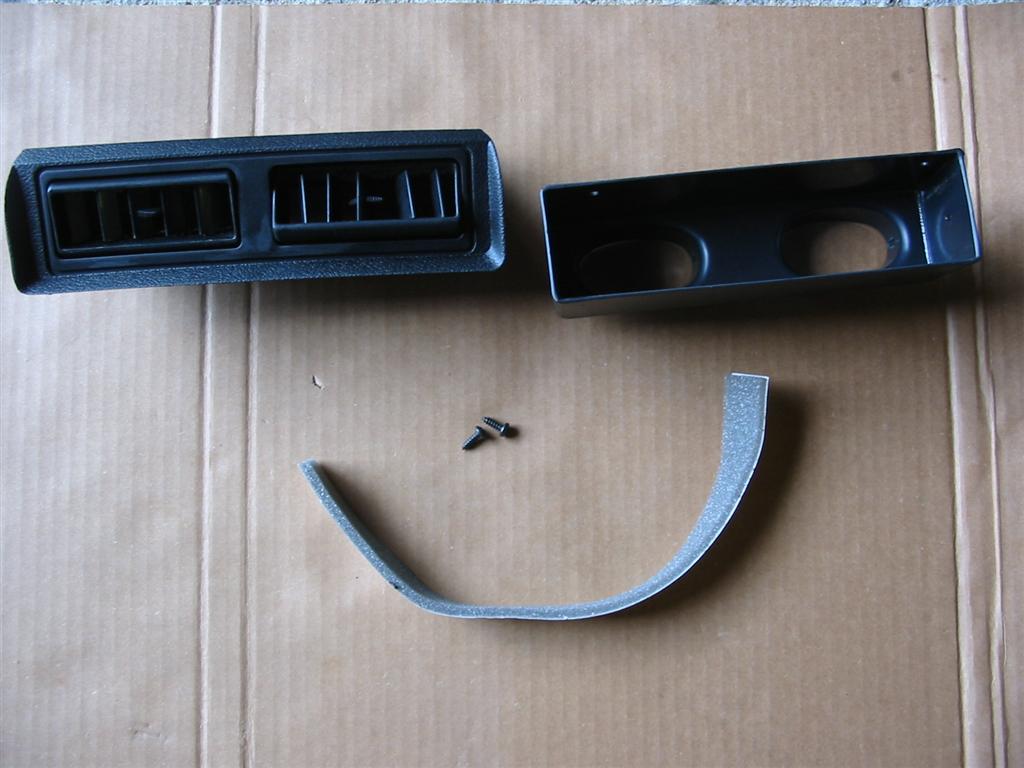
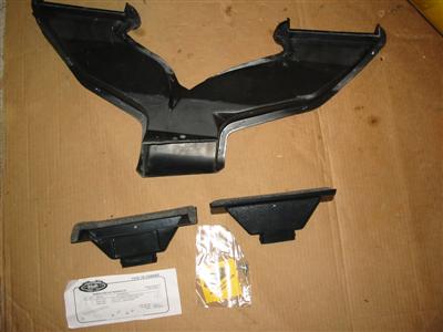
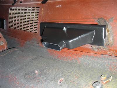
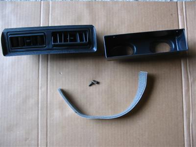
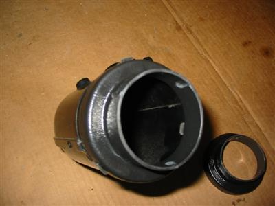
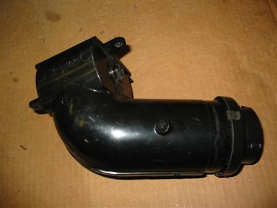
| Here are pictures of the factory and replacement defrost vents. The replacement vents
are smaller and easier to install than the factory unit. |
|
|
|
|
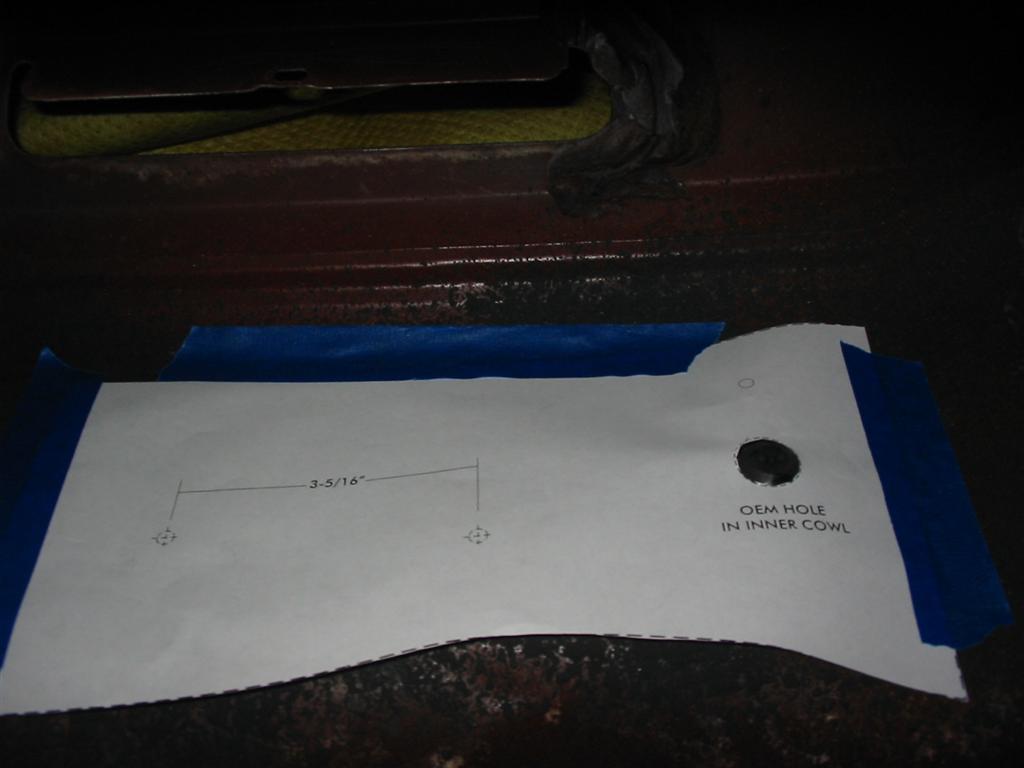
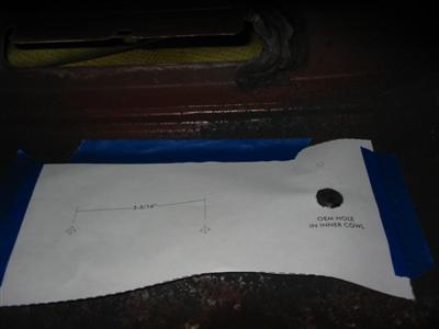
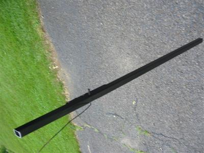
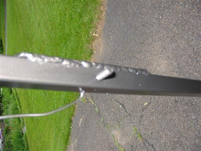
| The system is designed to have the evaporator mount under the dash by using screws that
mount into the cowl and by using a hole in the firewall to bolt to the bracket mounted on the
evaporator below. Unfortunately, my car was
complete and I had no plans to drill any new holes into my nice shiny smooth
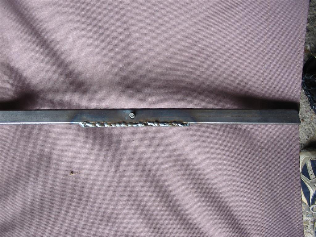
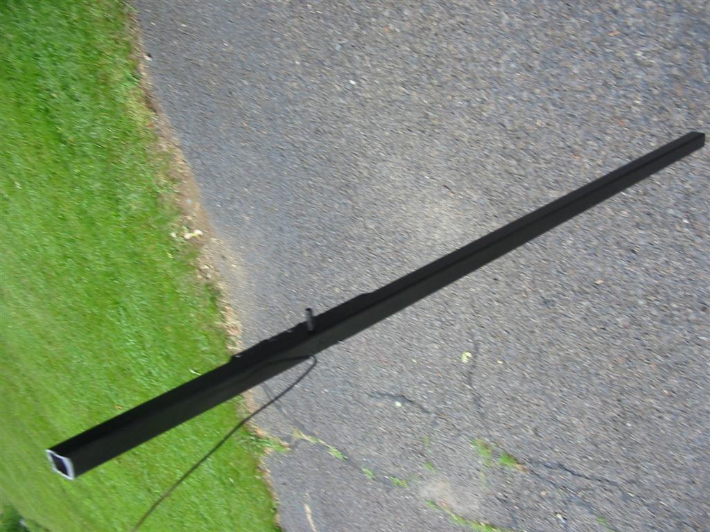
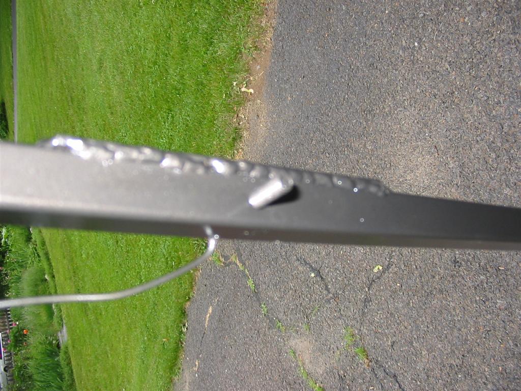
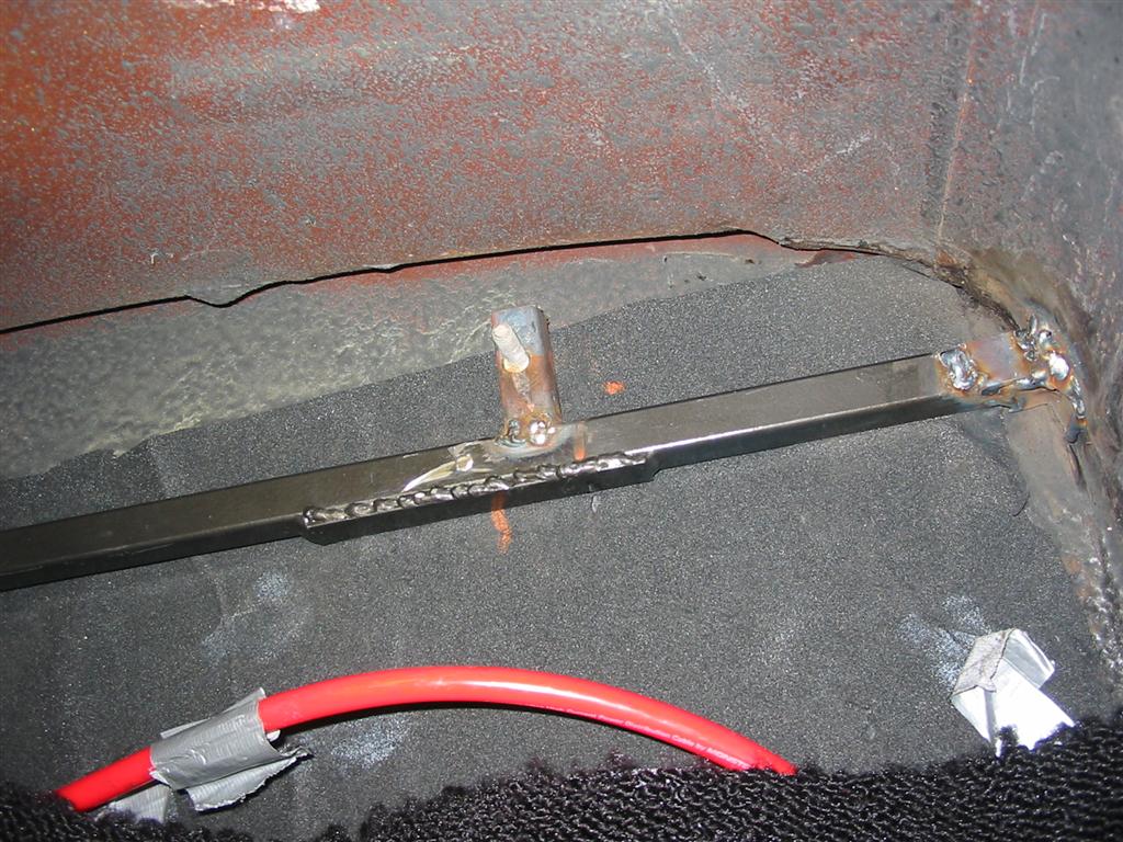
firewall. I decided to run a piece of square tubing across the firewall. I welded
the tube to the kickpanel on the passenger side and to the dash brace on the driver's
side. Originally, the tube was a straight shot across with a stud welded into it, but
I measured incorrectly and had to weld a vertical piece to my brace to mount the unit. |
|

|
|
|

|
|
| At this point, I was still waiting for my hidden hose pieces so I started working on the
center vents. This system utilizes the factory center vents. I had to do some minor
clearancing of the hole for the screws used to mount the adapter to the factory vent. |

|
|

|
|
|
|
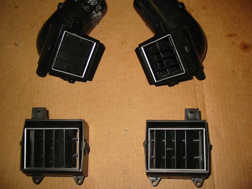
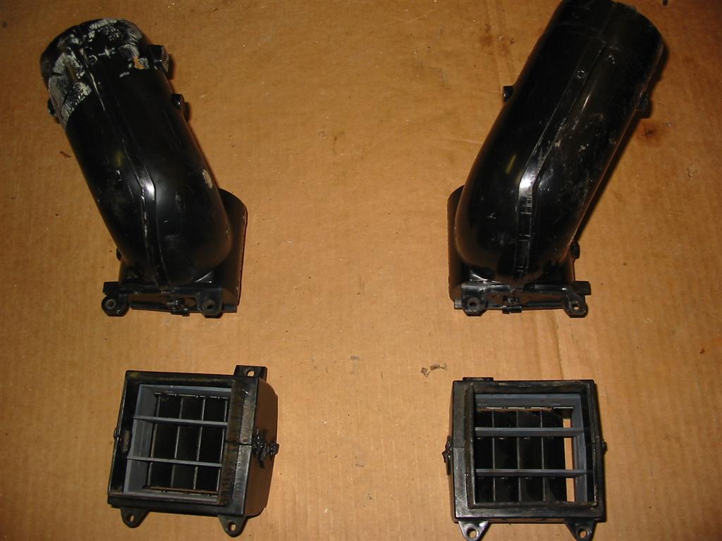
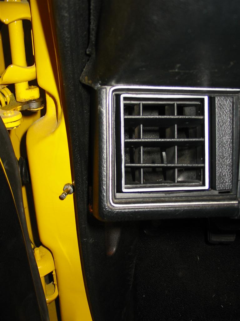
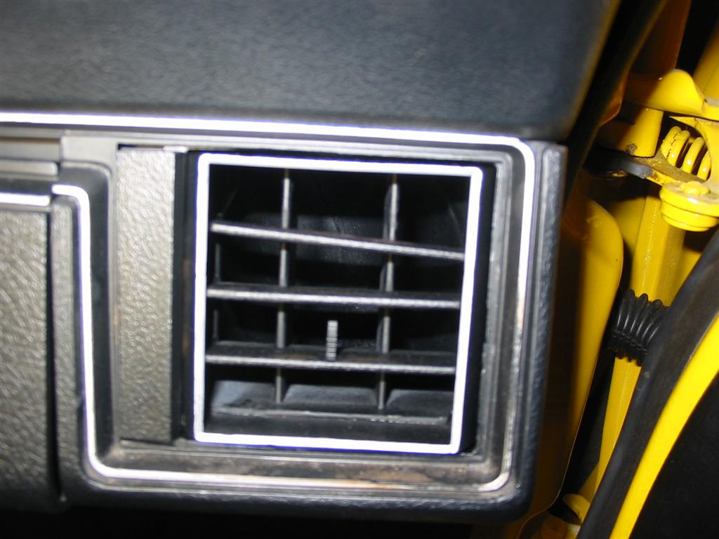
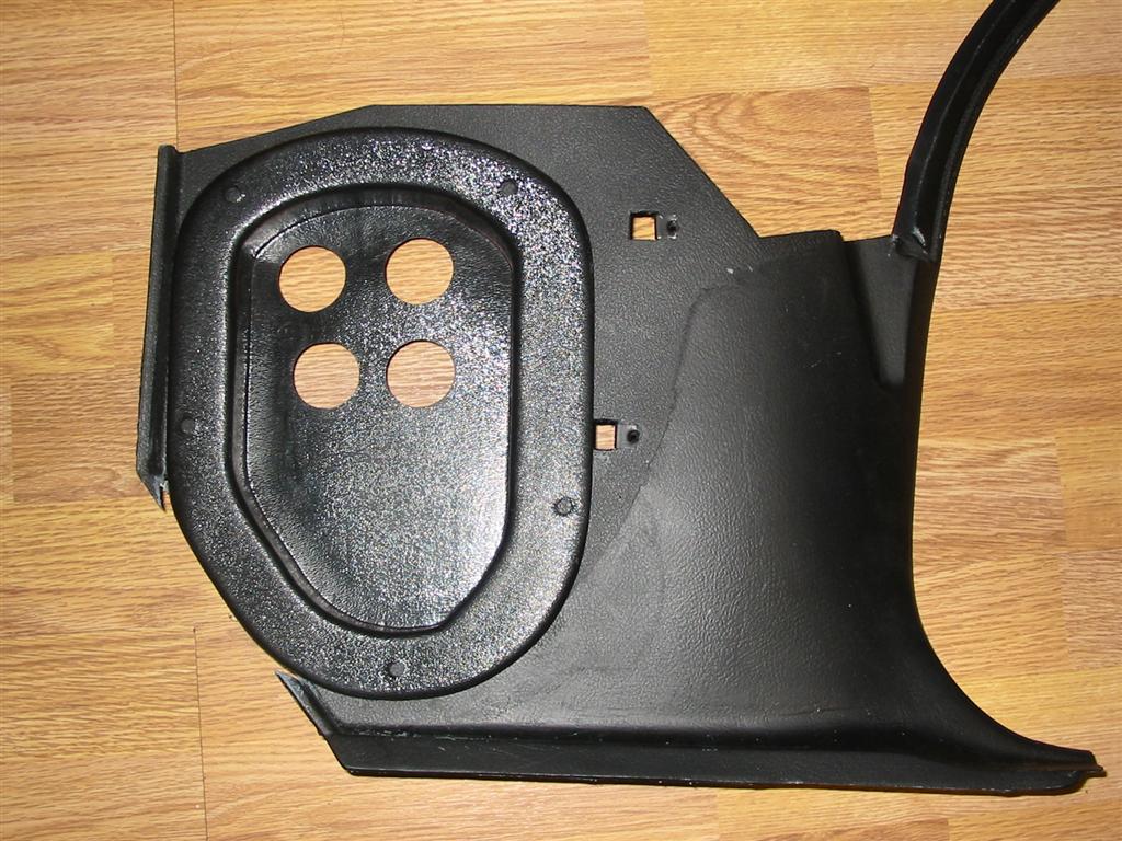
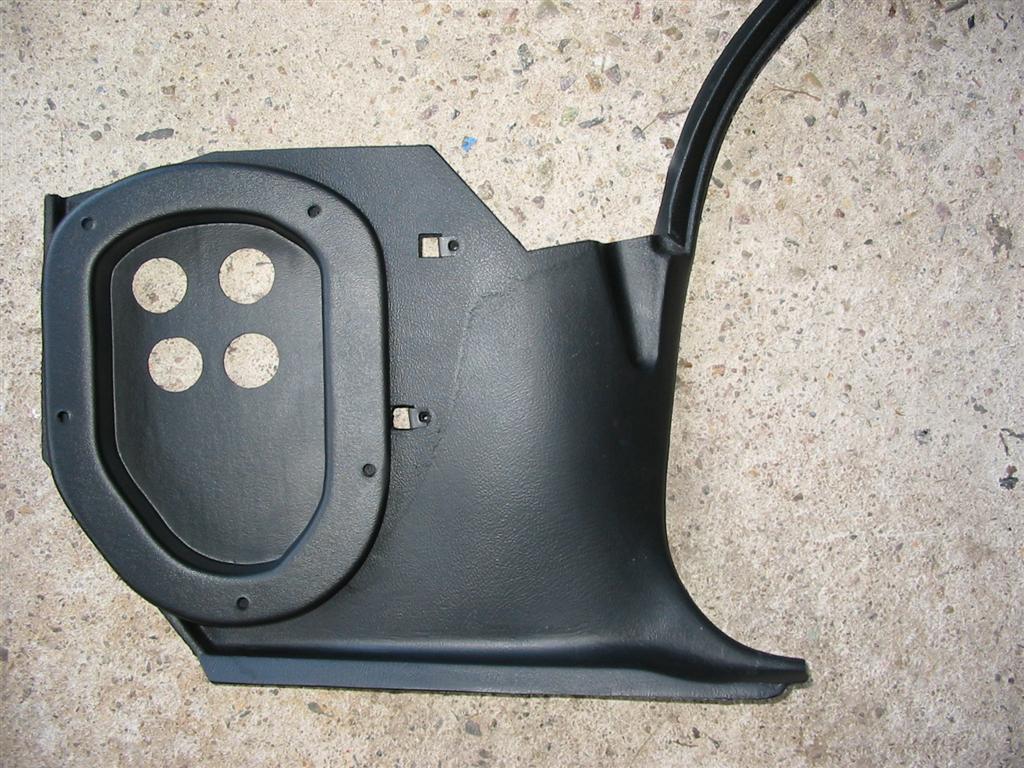
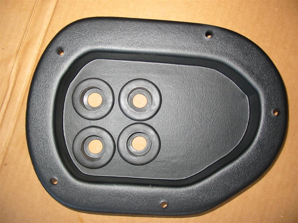
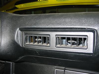
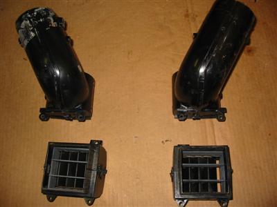
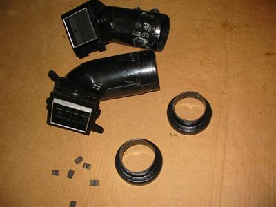
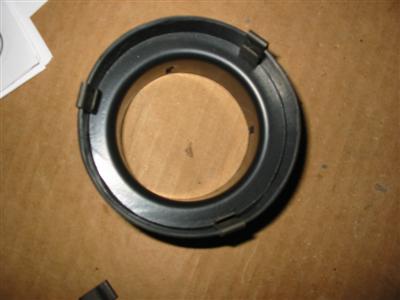
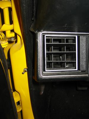
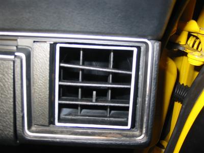
| When I built my car, I had interior pieces from my car and another parts car. When doing
this installation, I found out that I had installed the side dash vents from a non
A/C car. Believe it or not, the side dash vents are totally different and the
mounts I had would not work. I needed to dig out my A/C vents and clean them up
and paint them. Here are pictures comparing the two vents and the installation of
the Vintage Air adapters being installed. |

|
|
|
|
|
|
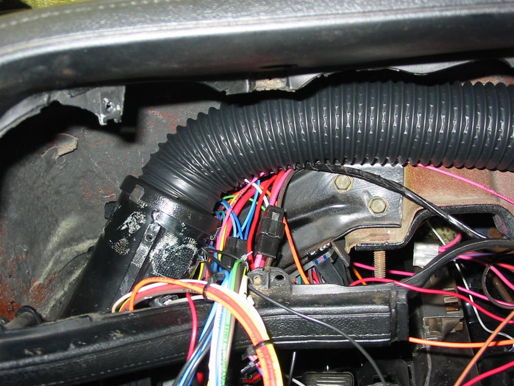
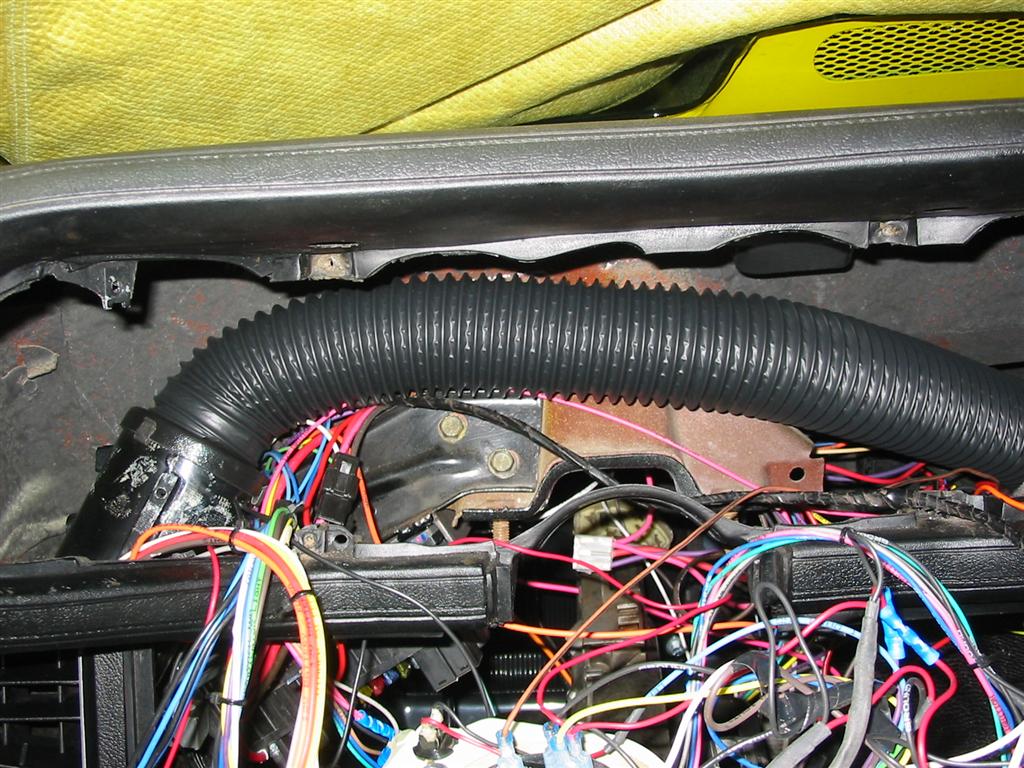
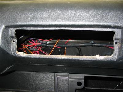
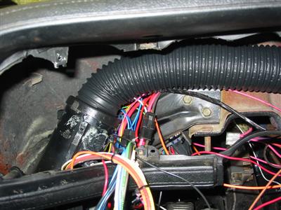
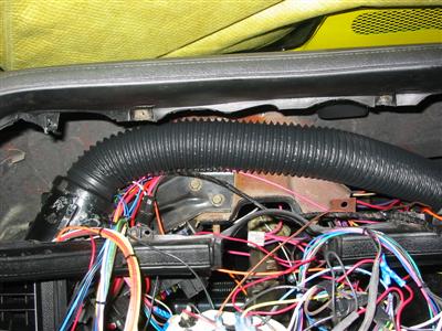
| Here is the hose that runs from the driver side vent dash to the evaporator unit.
This hose runs behind the dash panel. I also used this opportunity to clean up
some of the wires behind the dash. |
|
|
| Here are the side vents installed. |
|
|
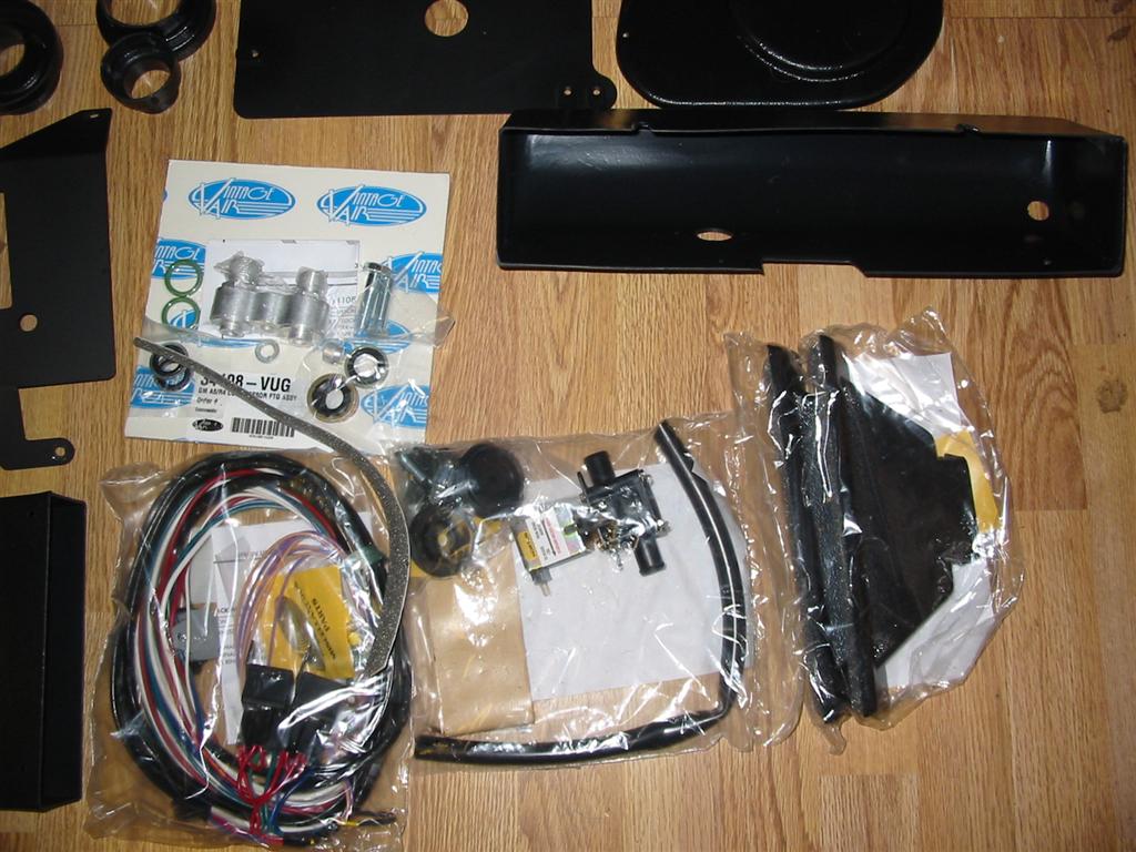
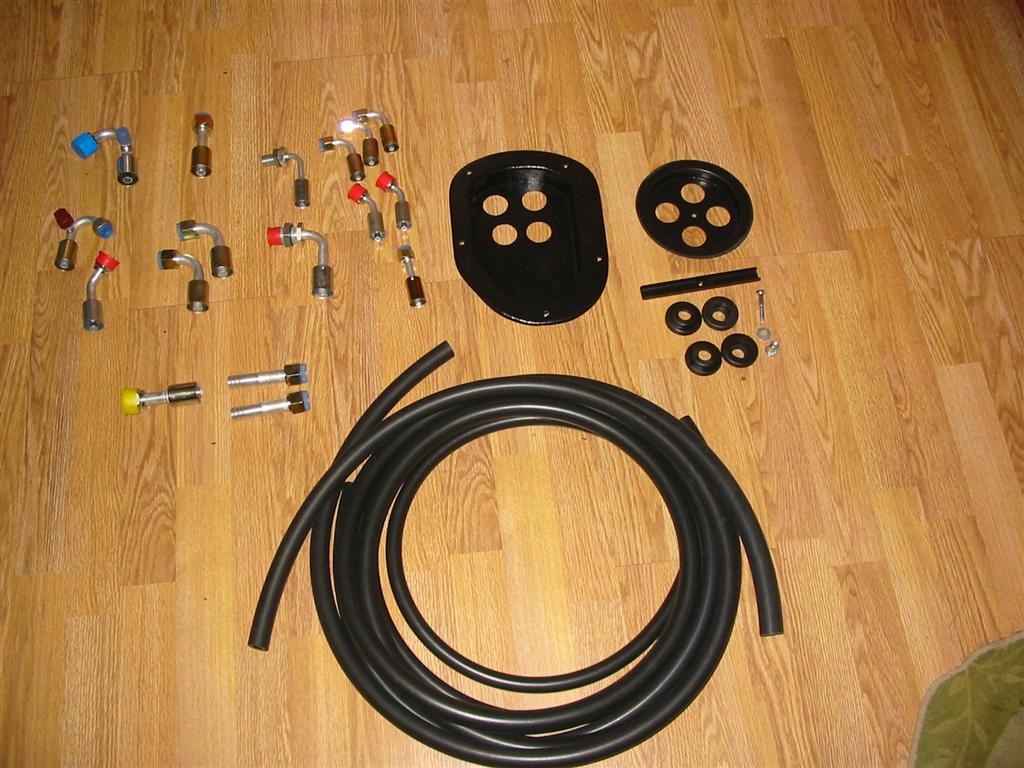
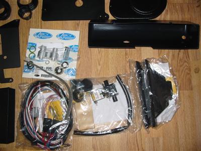
| Here are the components for the hidden hose option. |
|

|
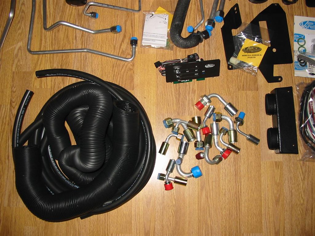
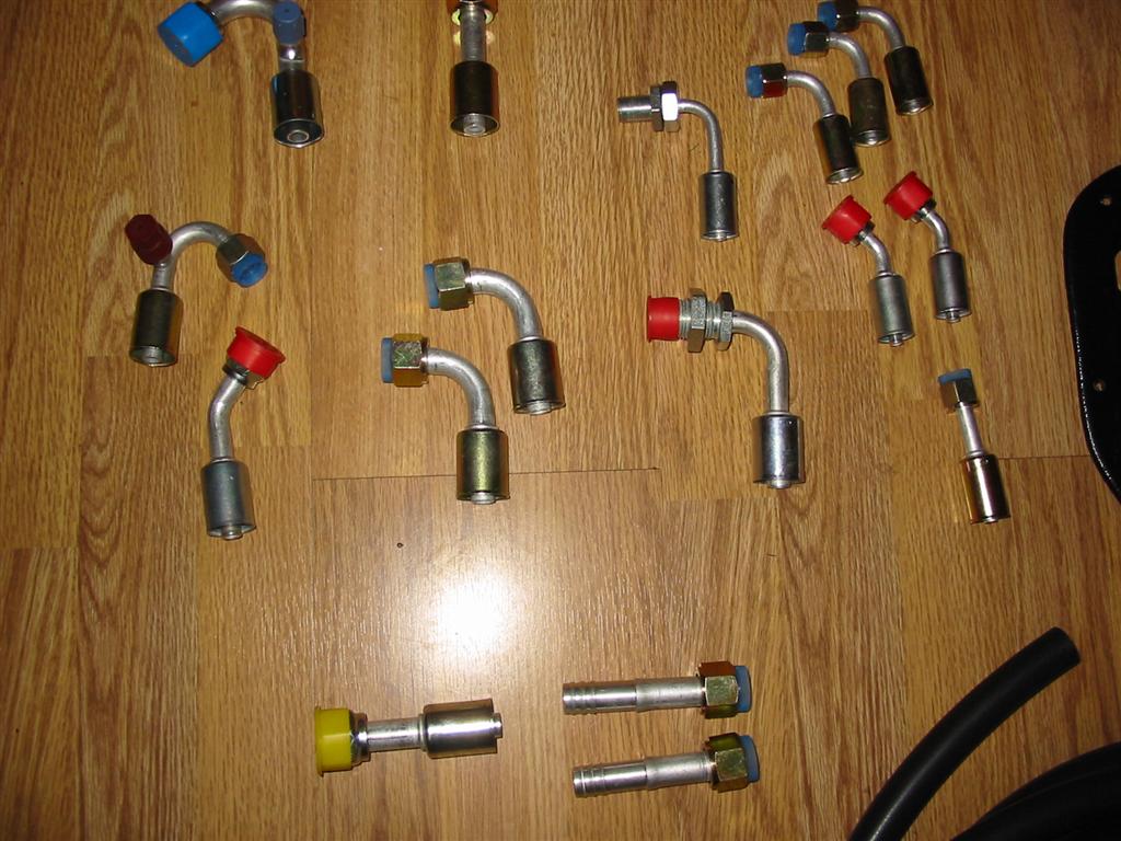
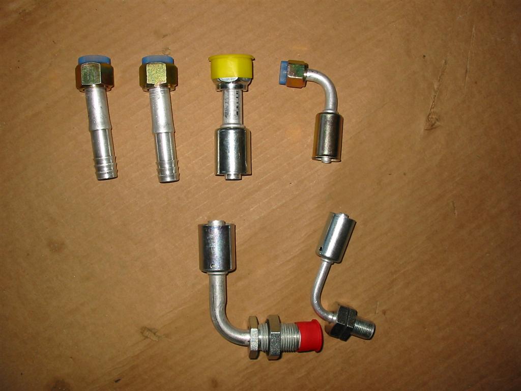
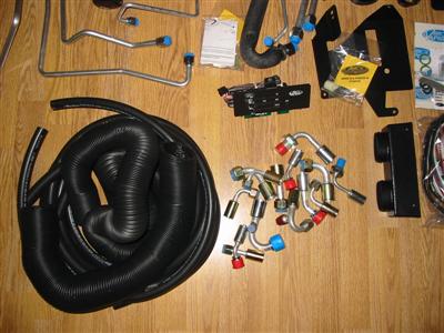
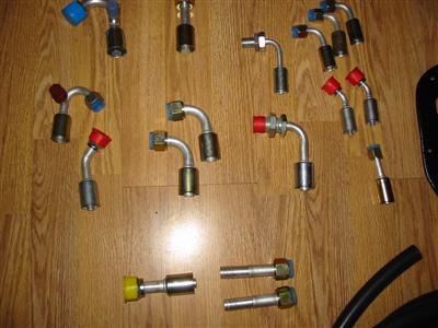
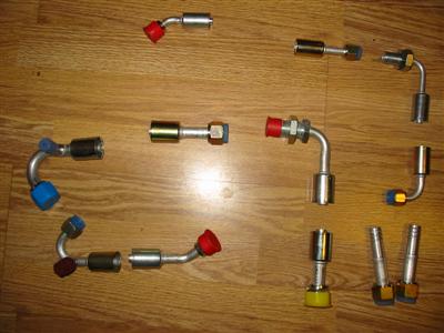
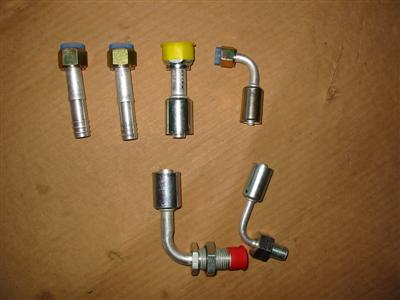
| Here are all the fittings that were included in the system including the ones that came with the
hidden hose option. |
Here are some extra fittings that Prodigy sent me to complete the installation. |
|

|
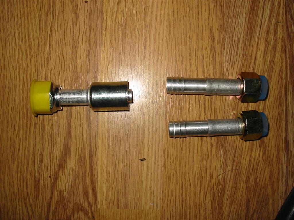
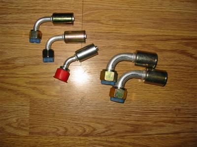
| Here are the fittings that I wound up using. My final installation would require
5 A/C lines and 2 heater lines. |
|
|
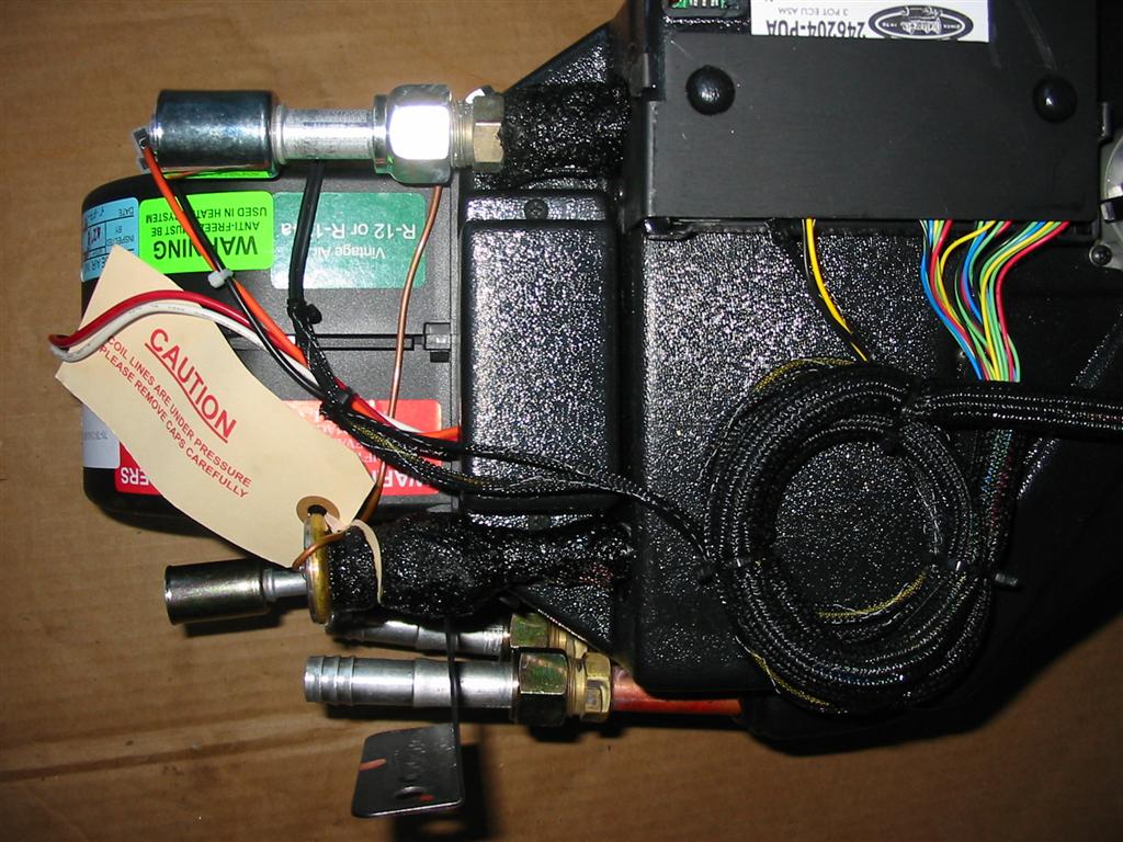
| When not using the hidden hose option, the following fittings below get mounted to the
evaporator unit and the 2 A/C fittings and the 2 heater hose fittings protrude
through the firewall. These fittings were not used in my installation. |
|
|

|
|
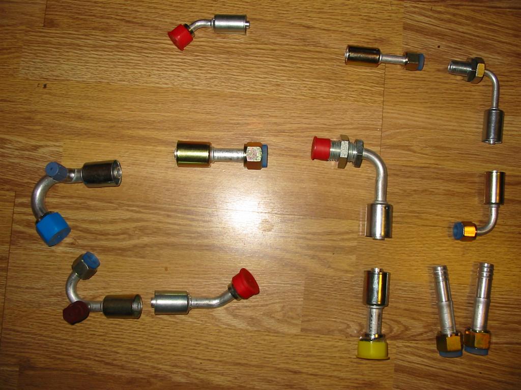
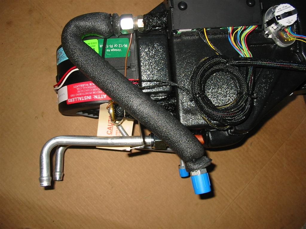
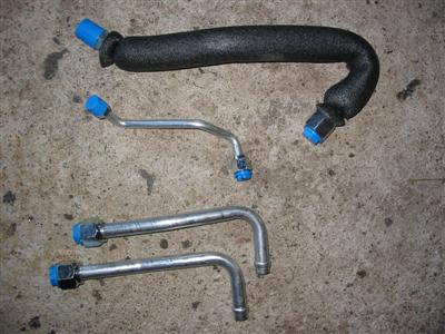
| Here are the fittings I used for the A/C and heater hoses that get attached to the
evaporator unit. I chose to run bulkhead fittings on the A/C lines and have a junction
in my fenderwell for them. For the heater lines, I just ran them straight through
grommets in the firewall in the fenderwell. Prodigy did recommend to just run all
4 hoses through the grommets in the firewall and I believe that would have worked fine.
I just wanted a place where I could easily replace a line if the line ever developed a
leak under the hood. I am pretty sure that the hose will never develop a leak in
the cowl area, so I should never have to go in that area again. |
|
|

|
|
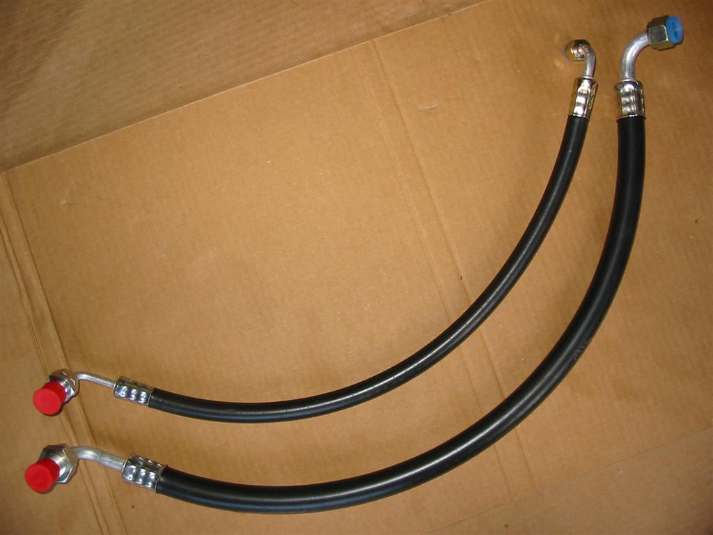
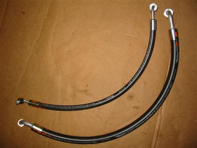
| The kit comes with hoses and fittings that need to be crimped on. Here are the
hoses that go from the evaporator unit to the firewall. I cut them and put
on the fittings so the hoses fit. I then marked the hoses and brought them
to NAPA to get crimped. |
|

|
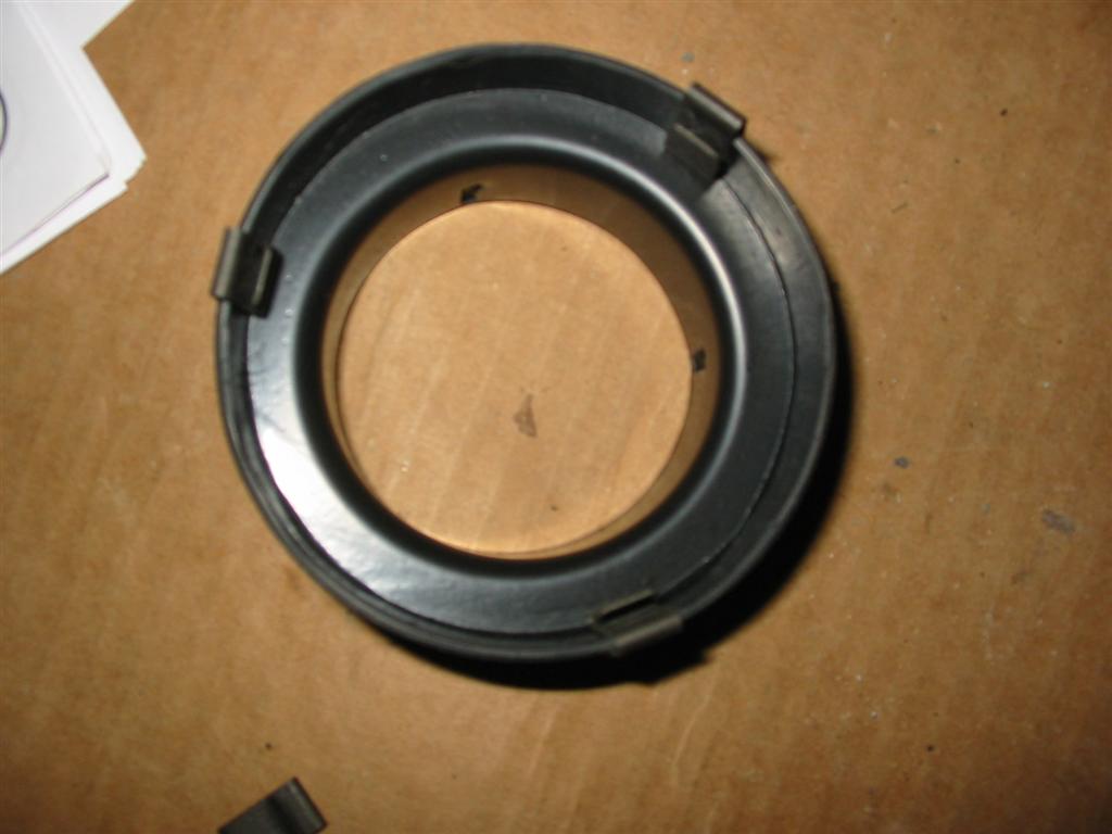
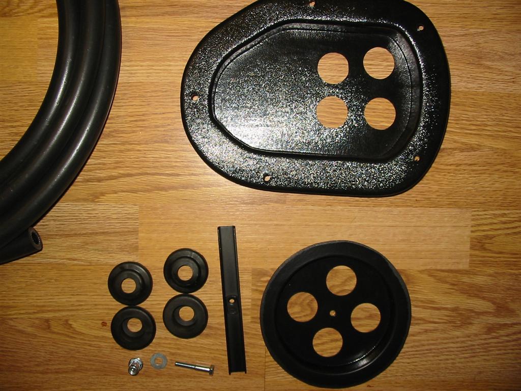
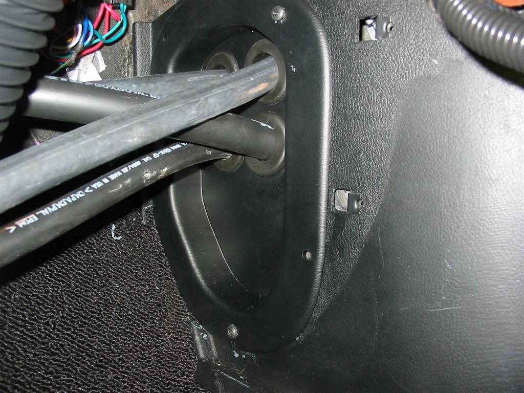
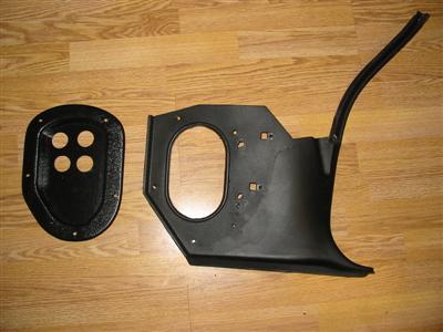
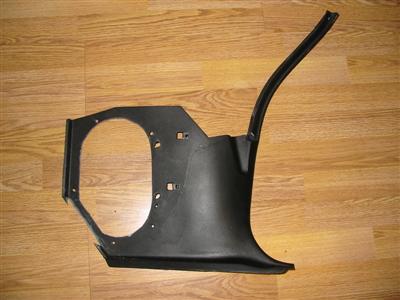
| Here are pictures of the kick panel insert that comes with the hidden hose option.
I had to modify the kick panel to accept the insert with the holes for the hoses. I
then dyed the insert to match the kickpanel. Lastly, I installed the included
grommets into the insert. |
|
|

|

|

|
|
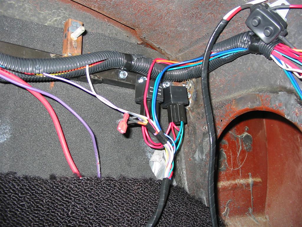
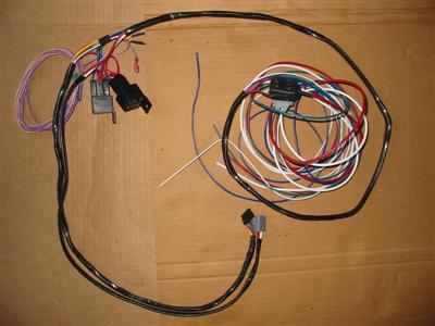
| Here is the harness that comes with the Vintage Air System. The system needs connections
to the following sources: Battery Power, Battery Ground and Ignition Power. The rest of
the harness connects to the unit with two plugs and to the compressor and heater
control valve under the hood. I mounted the relays and harness to the crossbar that I
installed to mount the evaporator unit. I also mounted the rest of my mess of wires
to this crossbar and put it in a neat harness. |
|

|
|
|
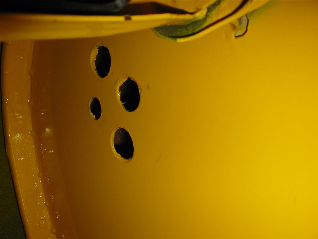
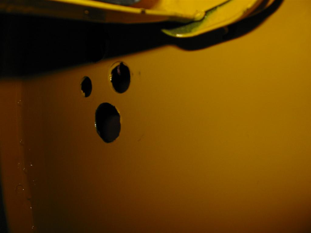
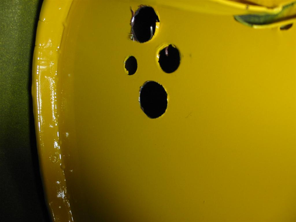
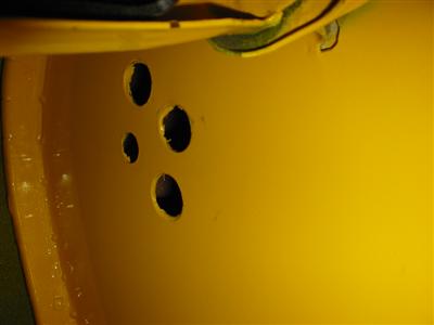
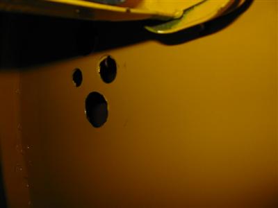
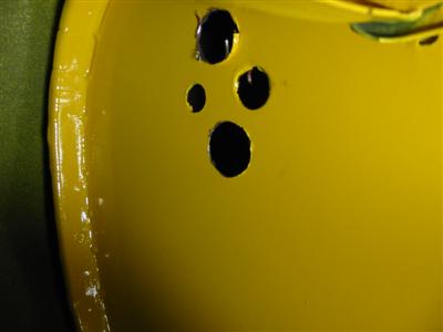
| The next step was to prepare the holes in my firewall for the A/C hose line with
bulkhead connectors and the grommets for the heater hoses. I already had a group of 4 holes
for the bulkhead that I previously installed. I didn't want to use the bulkhead because that would
have added 6 more connections in the system to leak. 4 for the heater hoses and an additional 2
for the AC lines. Unfortunately, my existing holes were too small for the grommets so I needed
to make them bigger using the step drill bit below. |
|

|
|
|
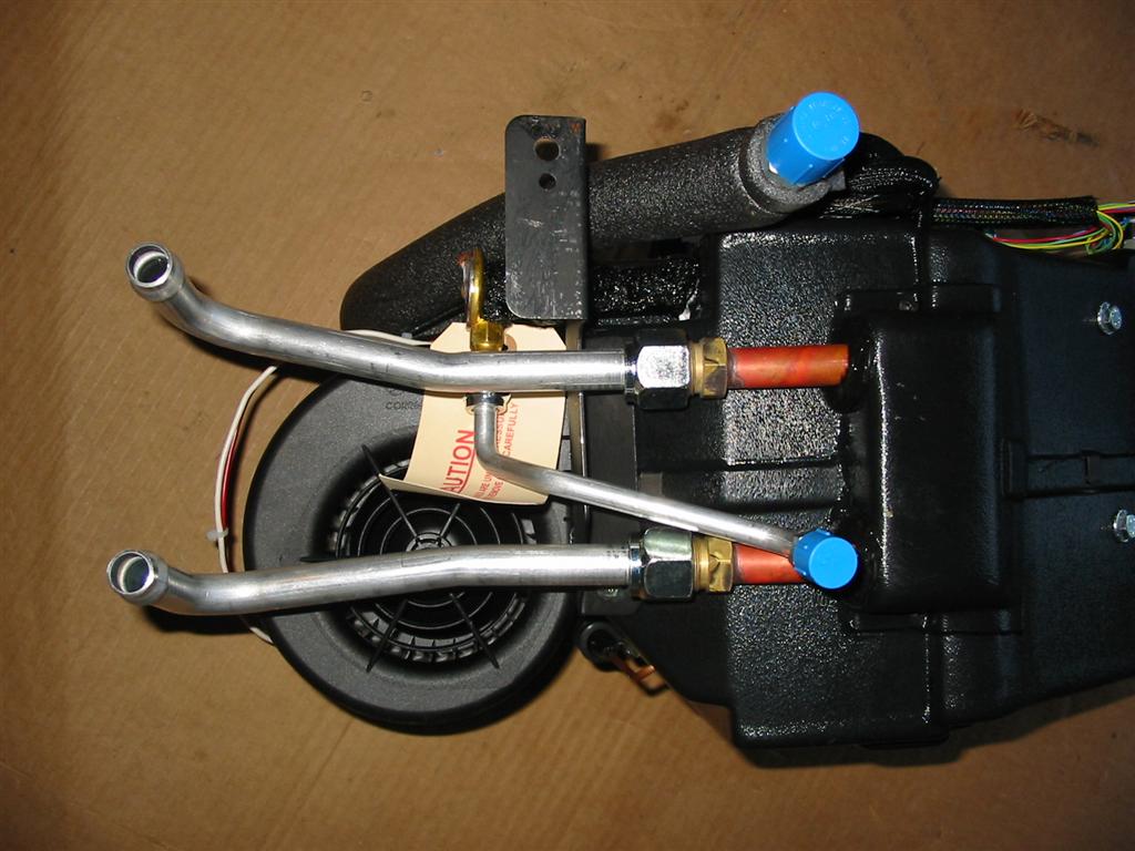
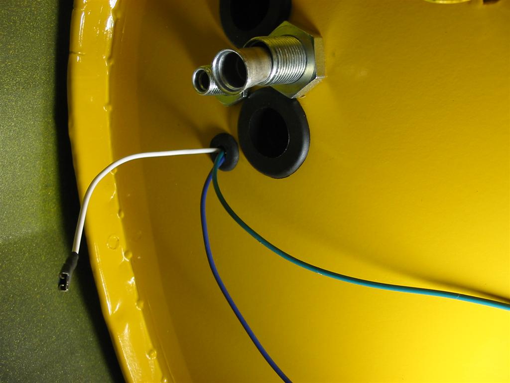
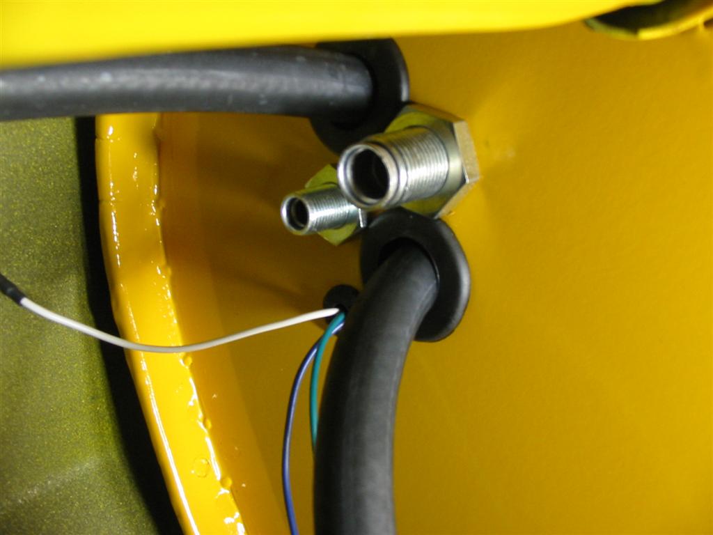
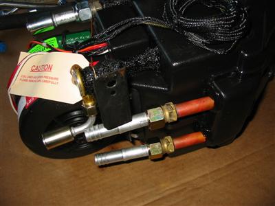
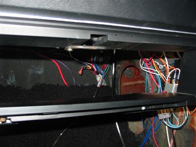
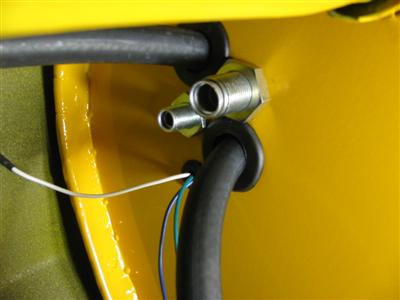
| Here are the A/C and heater hoses installed. I also decided to run the electrical out
through this area using a supplied grommet. These are the connections for the
compressor and the positive and ground for the heater control valve. |

|
|
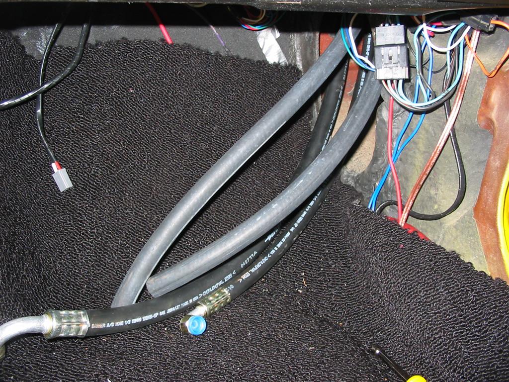
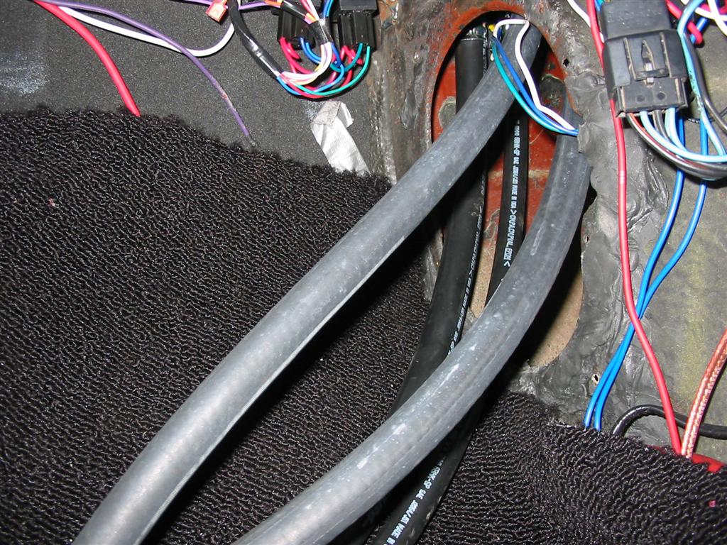
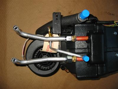
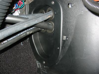
| Here are the A/C and heater hoses installed on the inside of the car. |

|

|
|
|