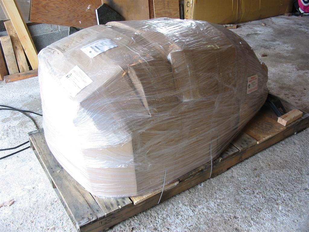
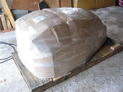
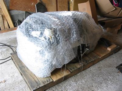
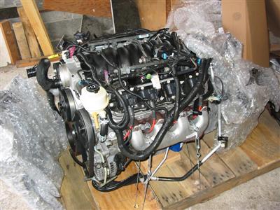
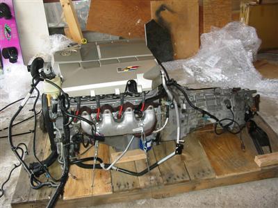
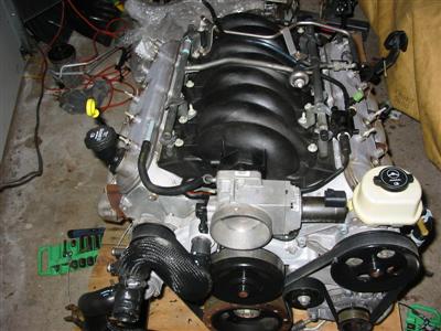
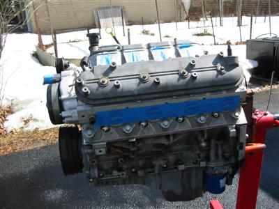
| Here is how everything showed up at my door. The driver pulled the crate off of the truck
and put it in my garage for me. |
|
|
|
|

|
|
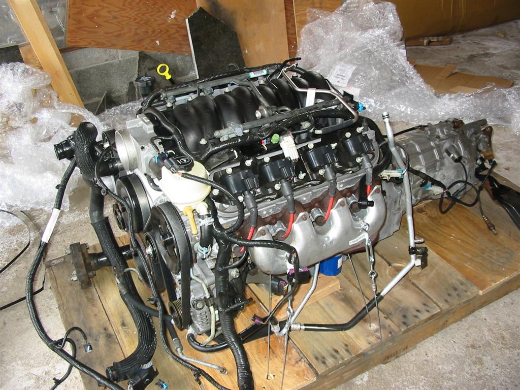
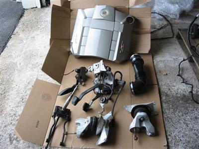
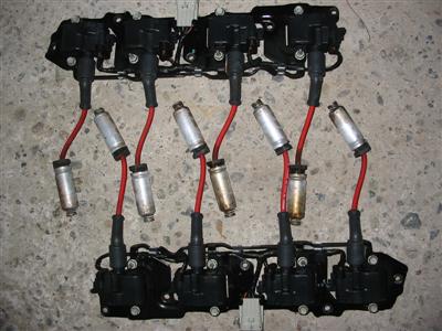
| Here are some of the extra items that were included on the pallet. |
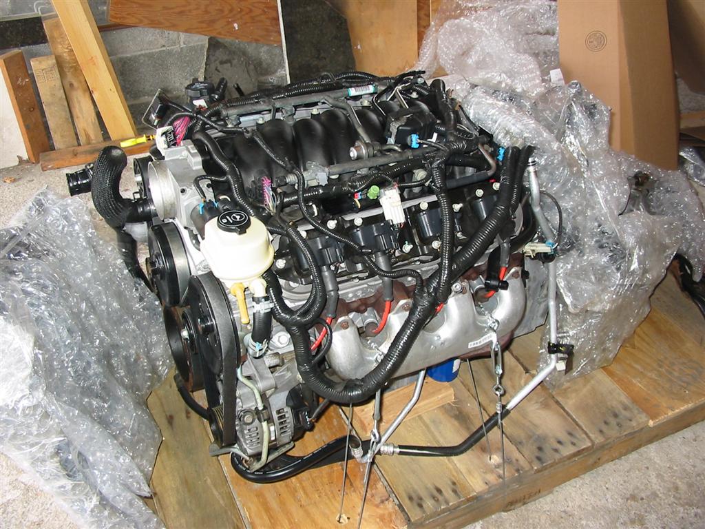
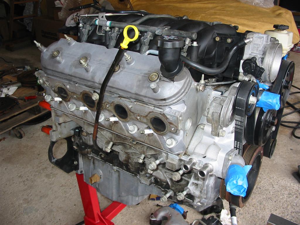
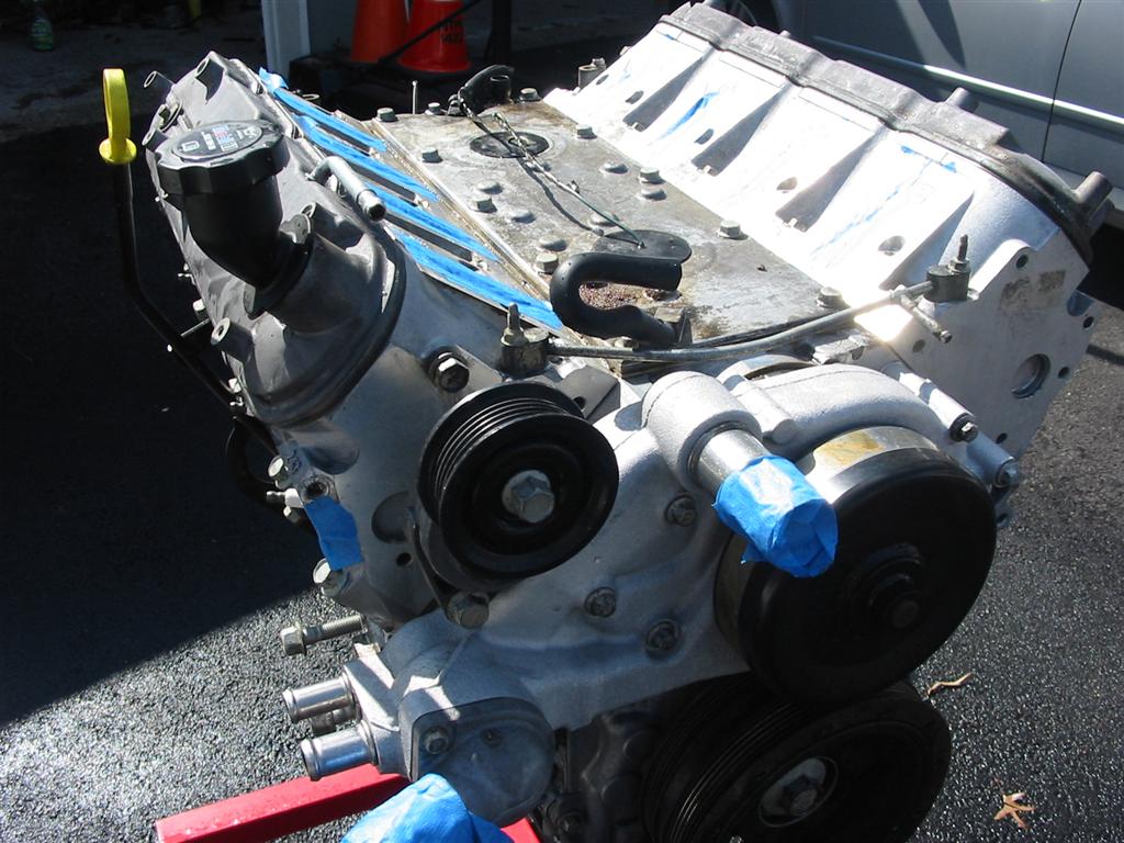
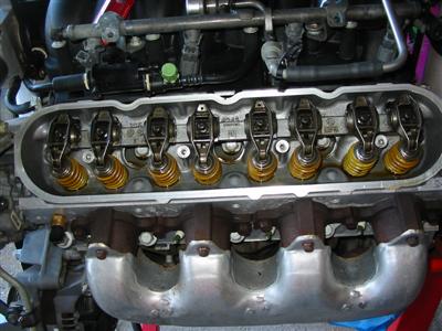
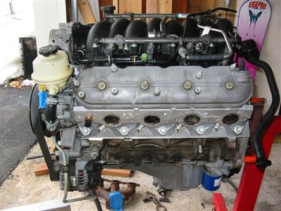
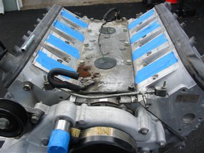
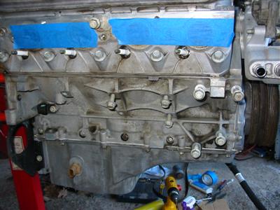
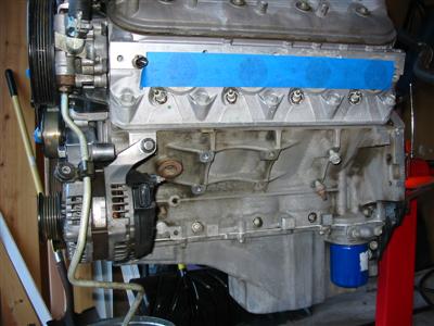
I wanted to pull a valve cover to see what the engine looked like. I was very happy to see that there
was zero sludge and everything looked clean and perfect. Tag Heuer Aquaracer Calibre 5 Replica
|
|
|
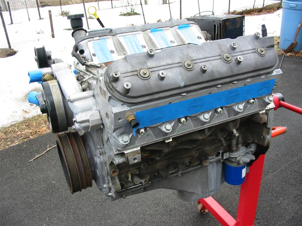
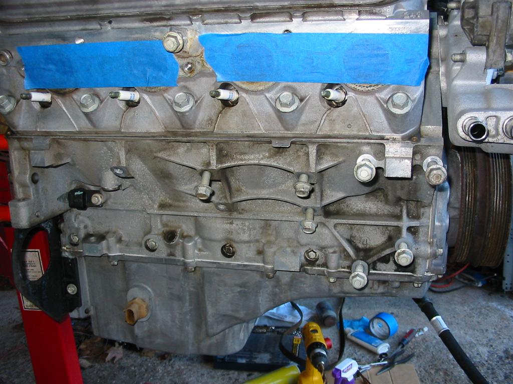
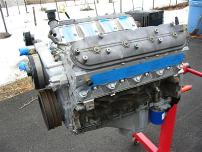
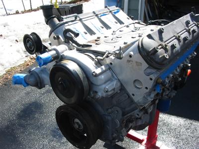
| I then started pulling all the bolt on pieces and accessories off of the engine to clean it
up. |
|
|
|

|
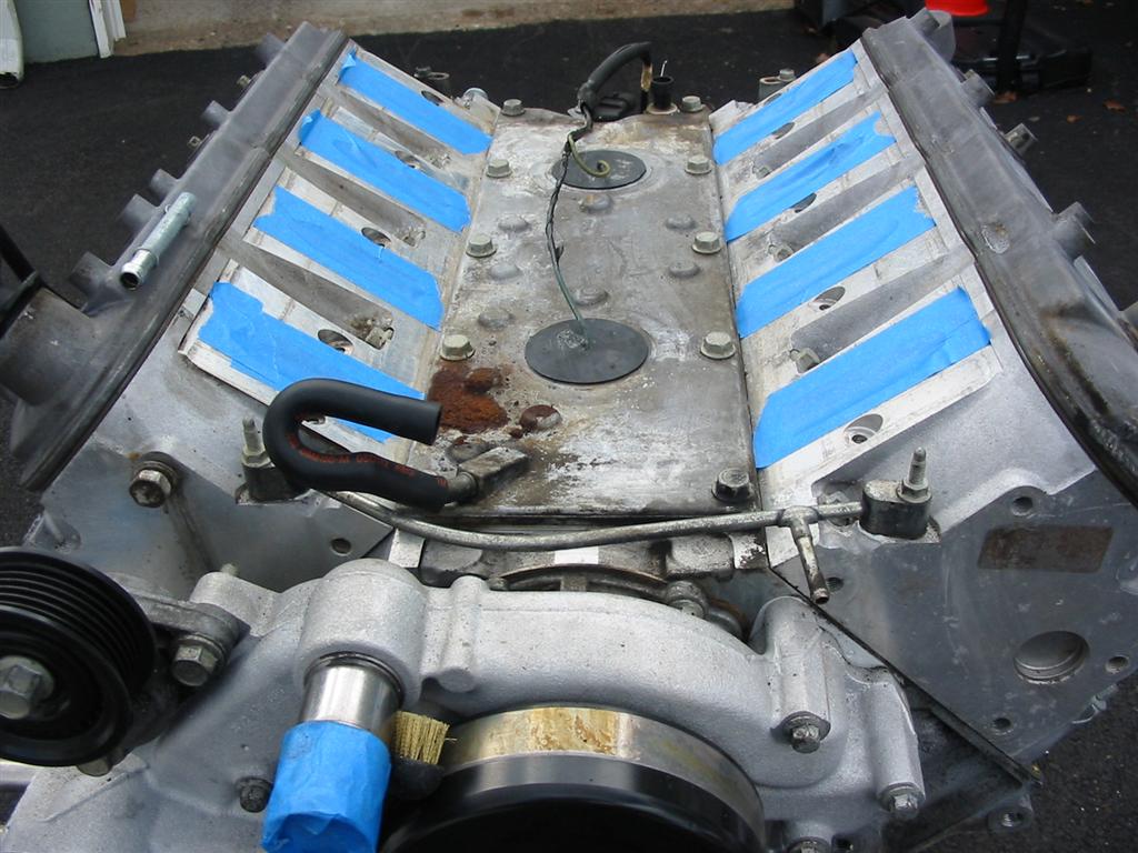
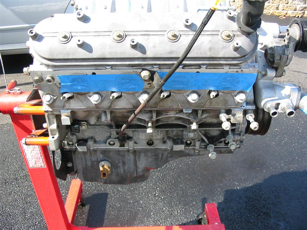
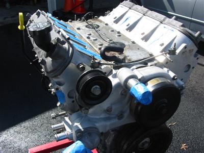
| Once the engine was stripped I cleaned it with various cleaning supplies, and brushes. |
|
|
|
|
|

|
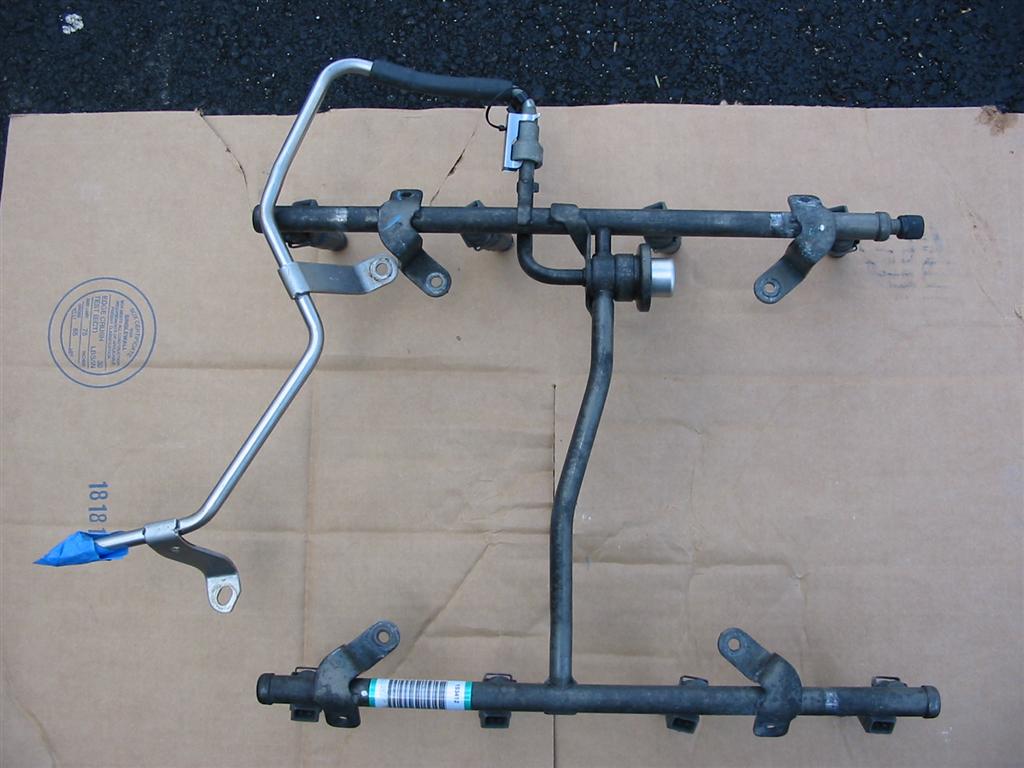
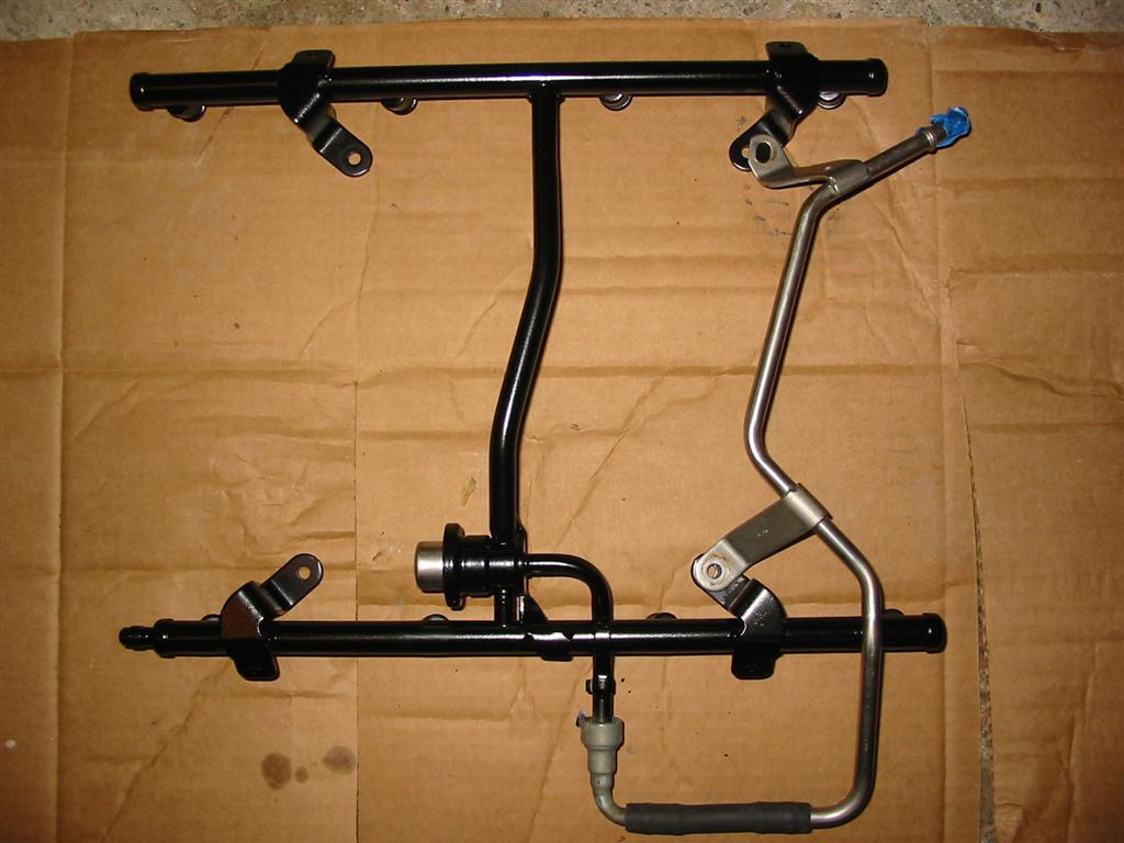
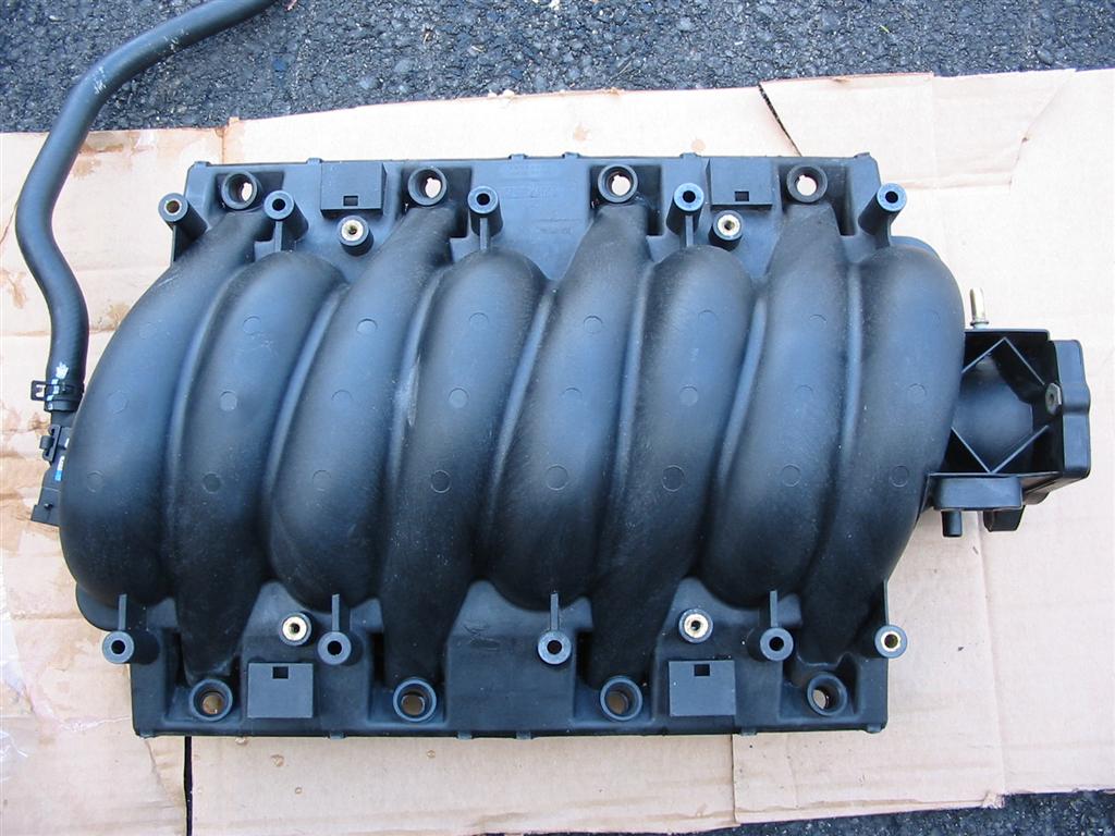
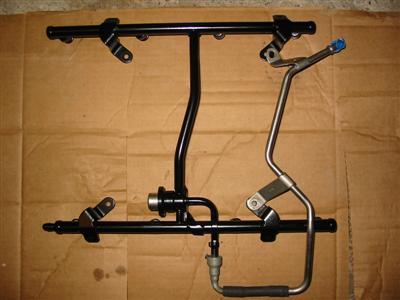
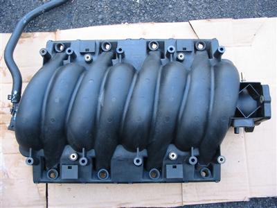
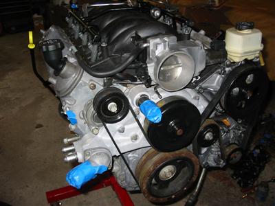
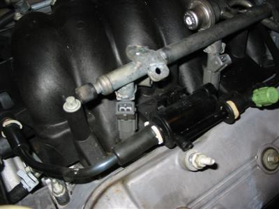
| I took this opportunity to clean the intake and injector rail. I also painted the injector
rail to make it look new again. |

|
|
|
|
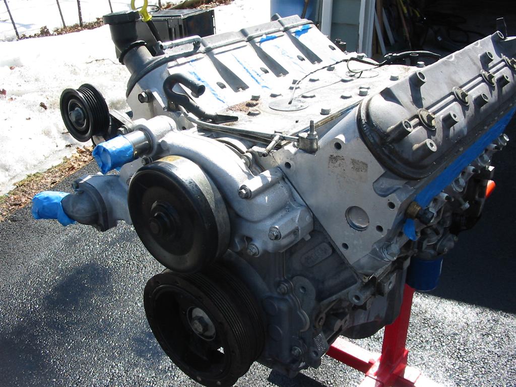
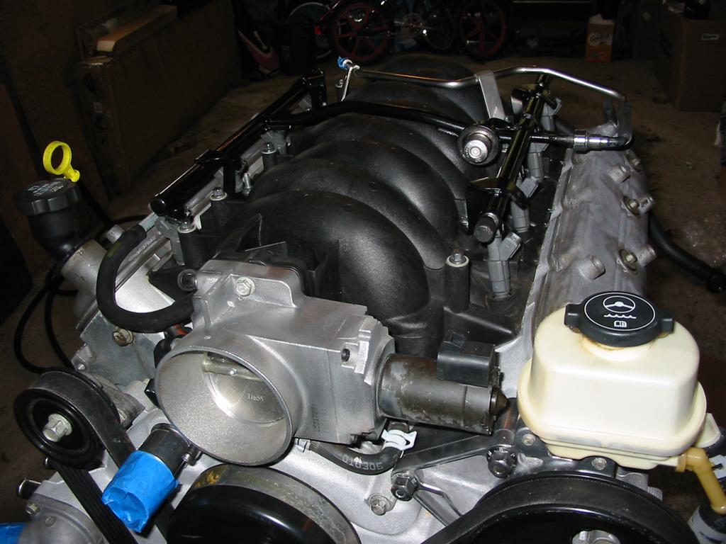
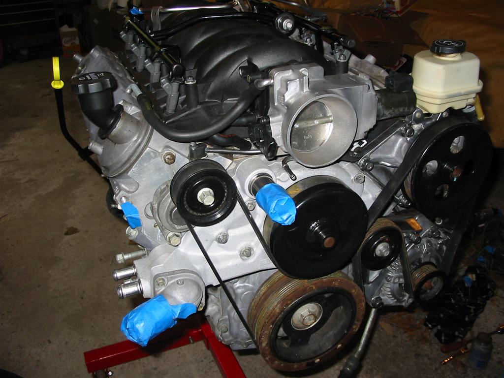
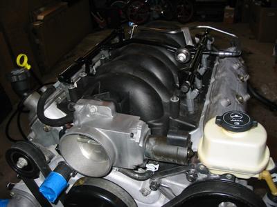
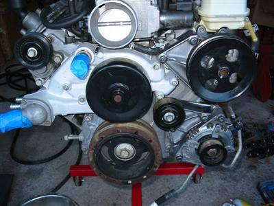
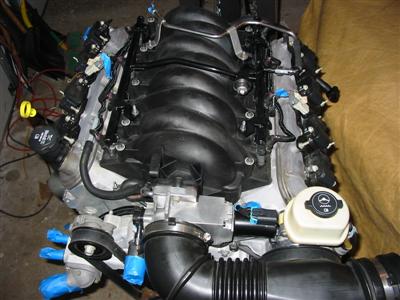
| Some more pictures of the engine and accessories cleaned up. |
|
|
|
|
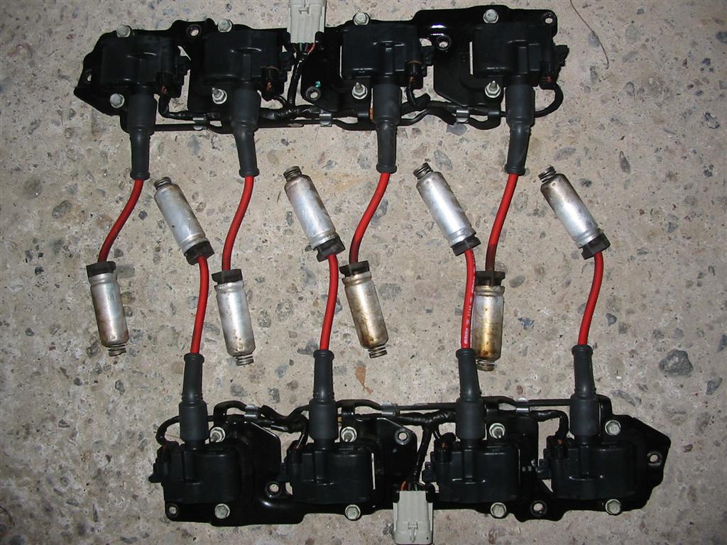
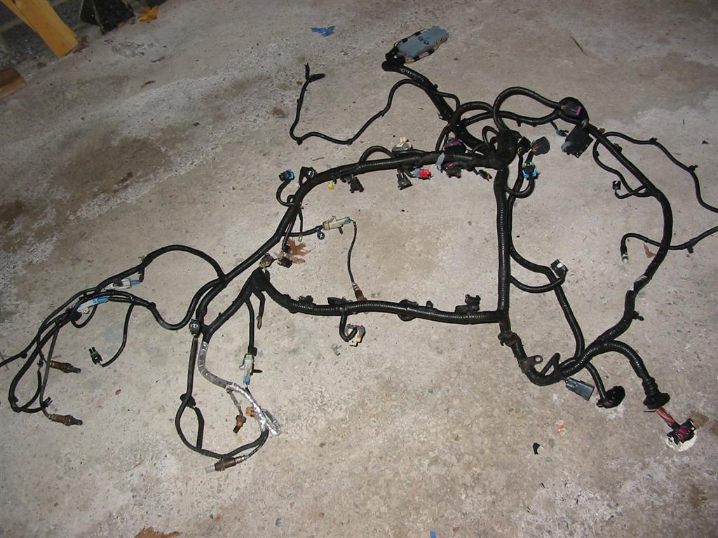
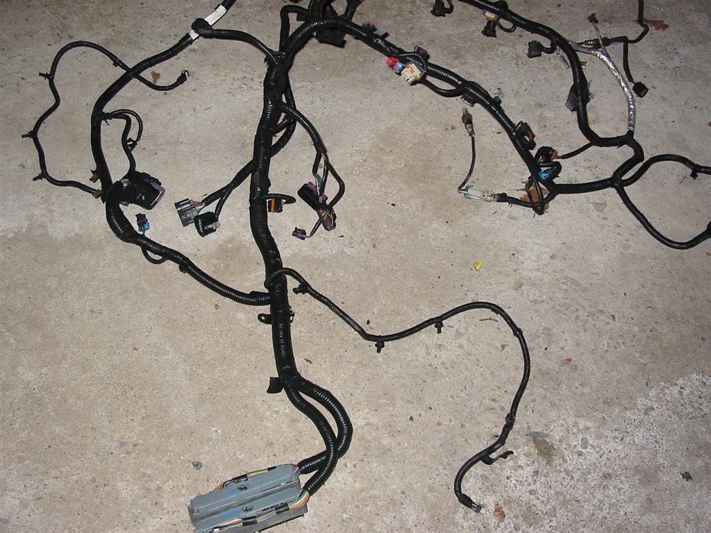
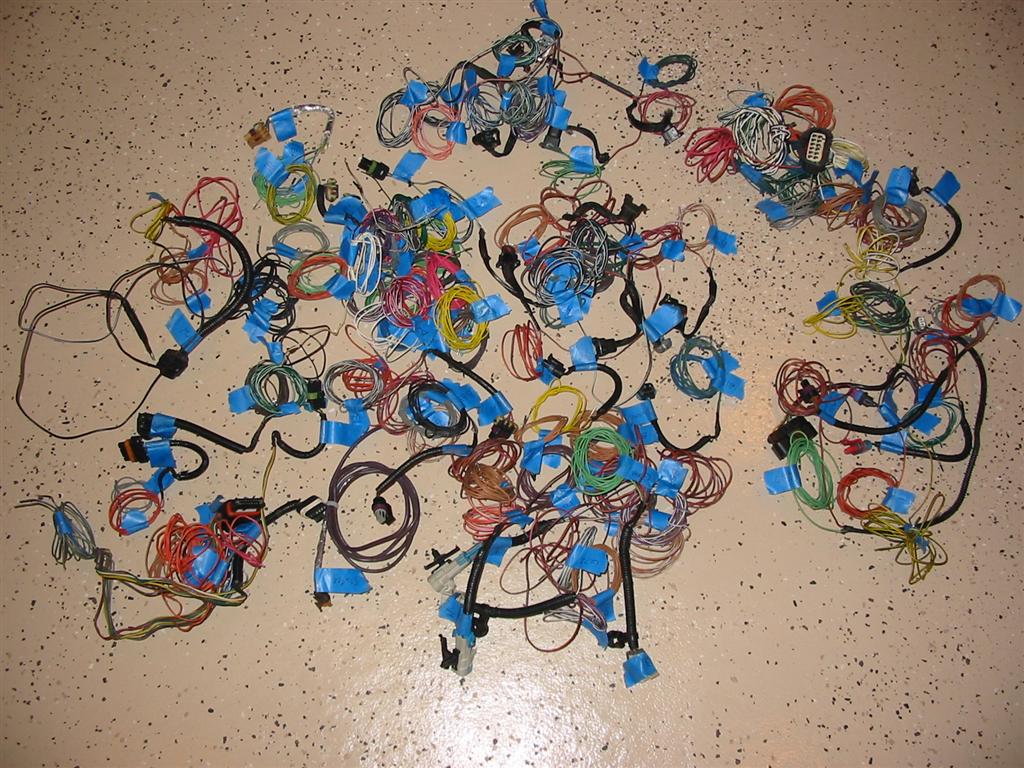
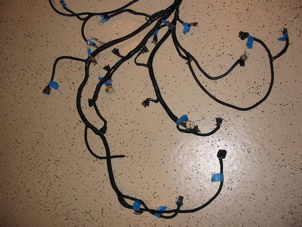
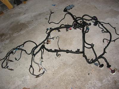
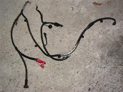
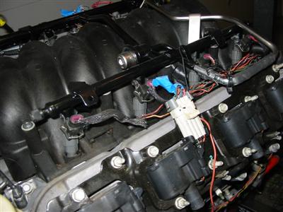
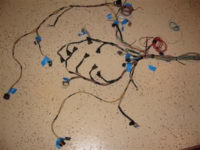
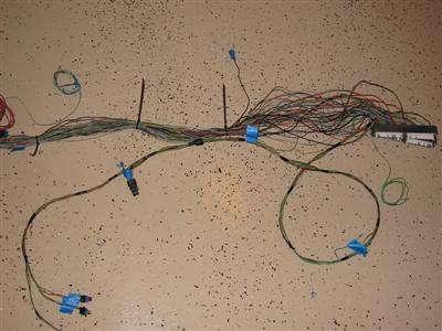
| Here are the before shots of the engine harness. |
|

|
|
|
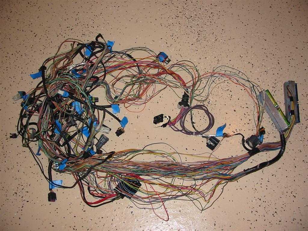
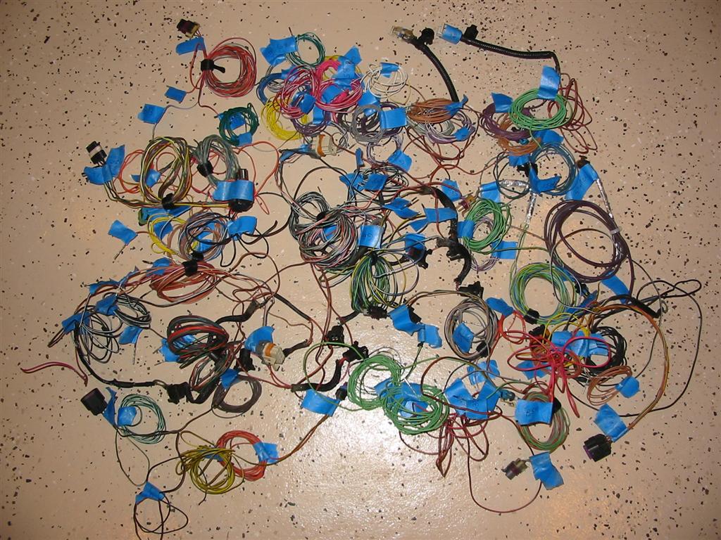
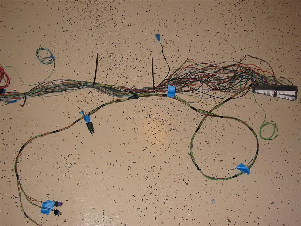
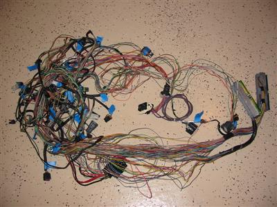
| The first step in building a custom harness is to remove all the tape covering the harness. |
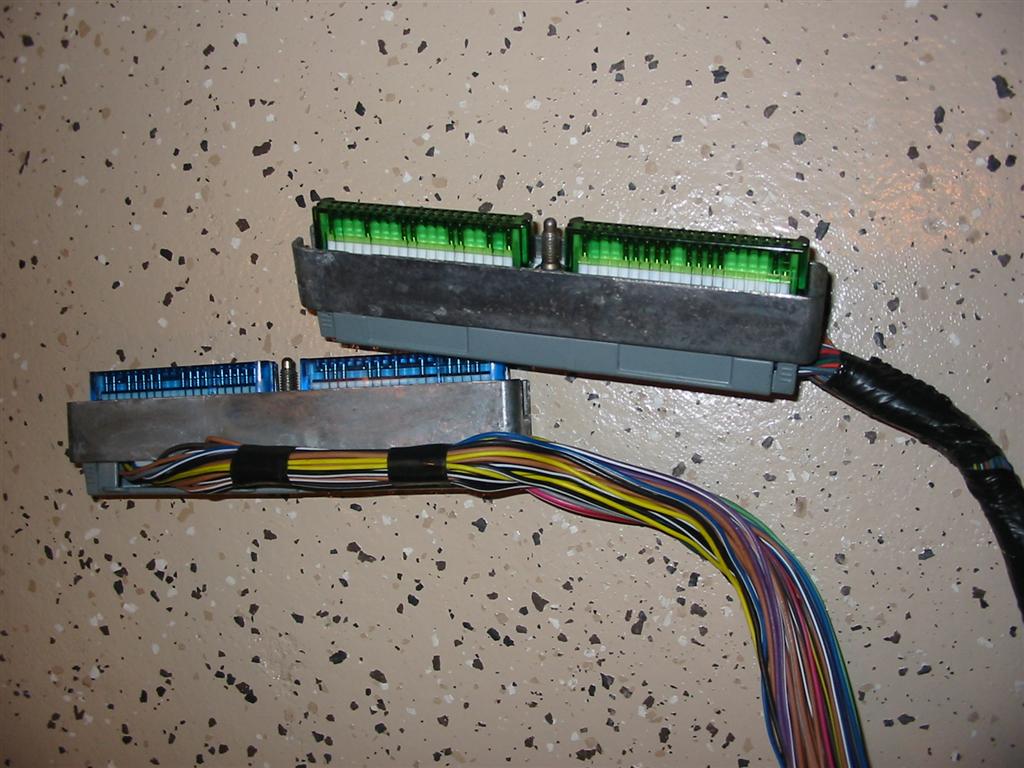
Here are the computer plugs. The next step is to pull the plugs apart and remove all the
wires and tag them. You also need a wiring diagram to match up the wires you pull off and verify that
they go to sensors that you are tagging them for. The wiring diagram will also help you in deciding
which ones you can remove. |
|

|
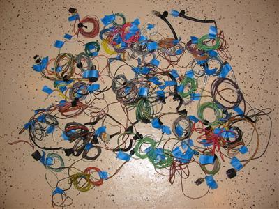
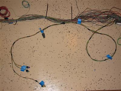
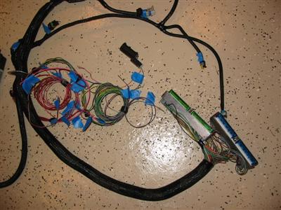
| Here are all the wires removed and tagged. |

|
|
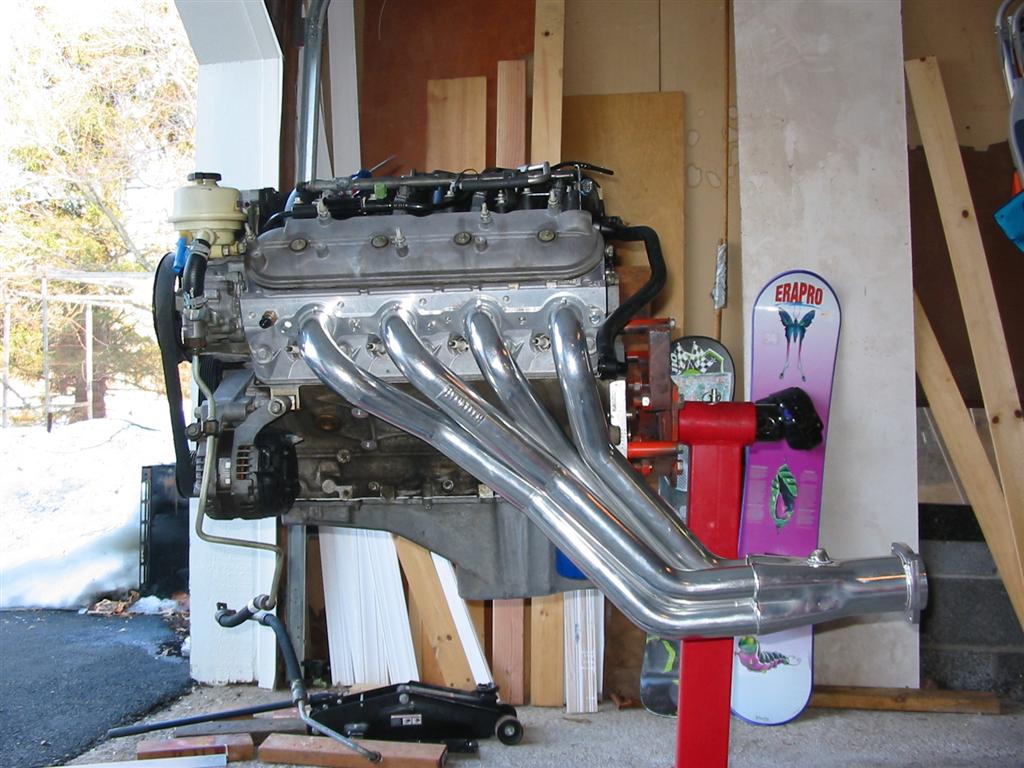
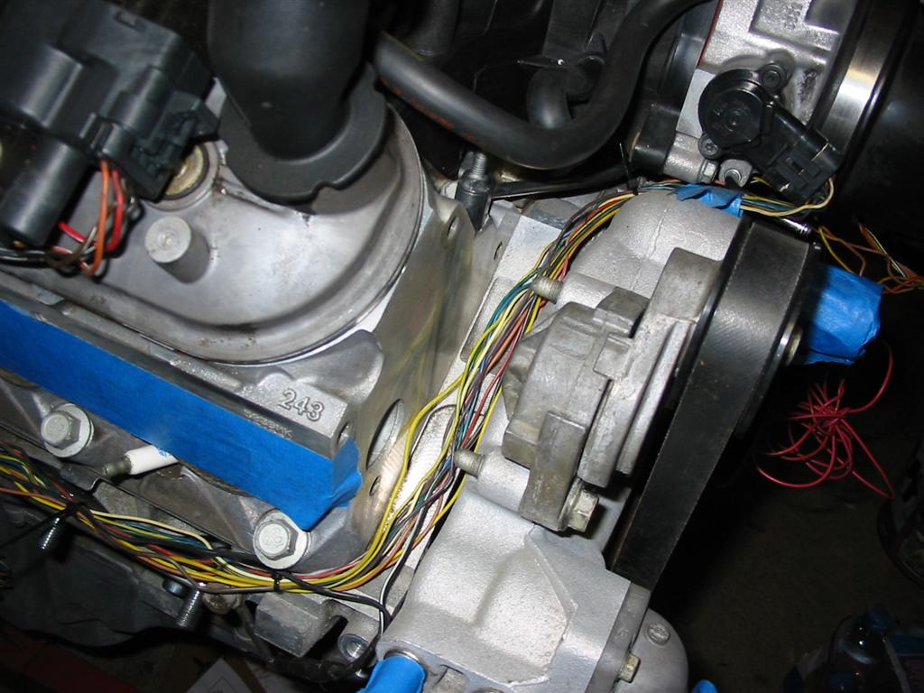
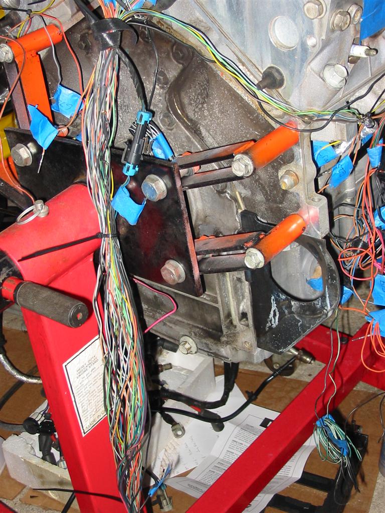
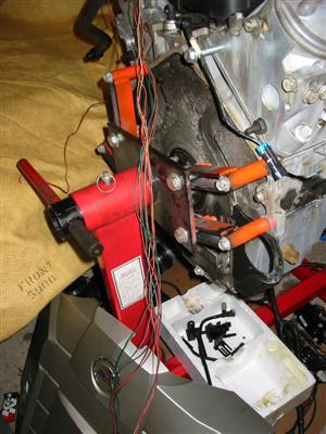
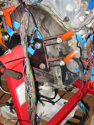
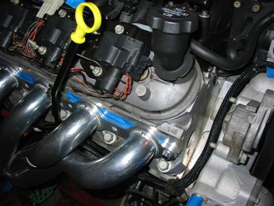
| For the next step in building the harness I installed a header on the engine. I then
plug the engine side plugs into the engine sensors one by one and run the wires back to
an estimated location to where I think I want the computer mounted. This is then used
to measure the lengths of each wire.
|

|
|
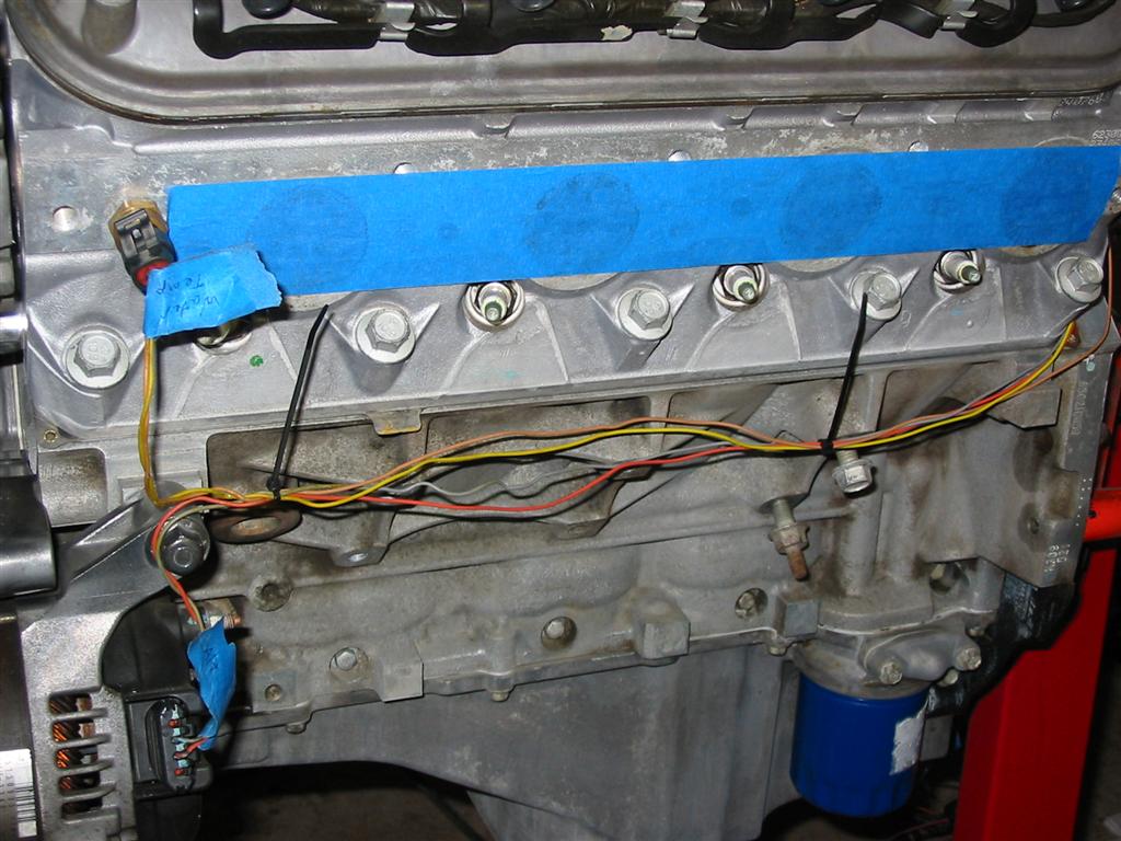
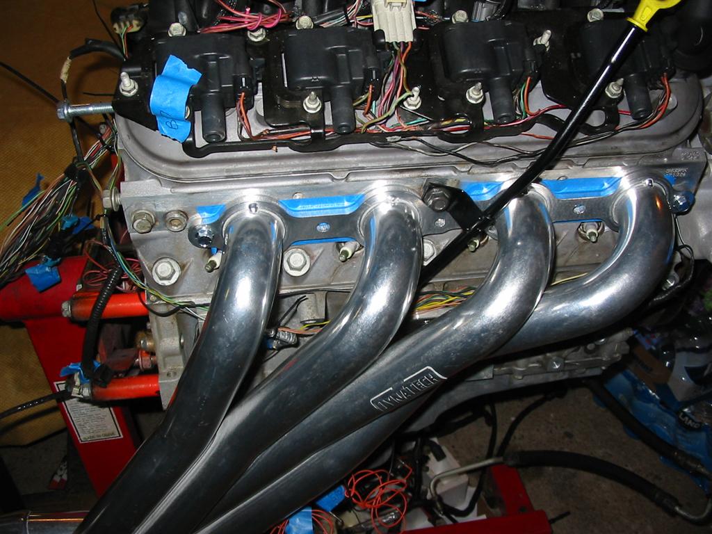
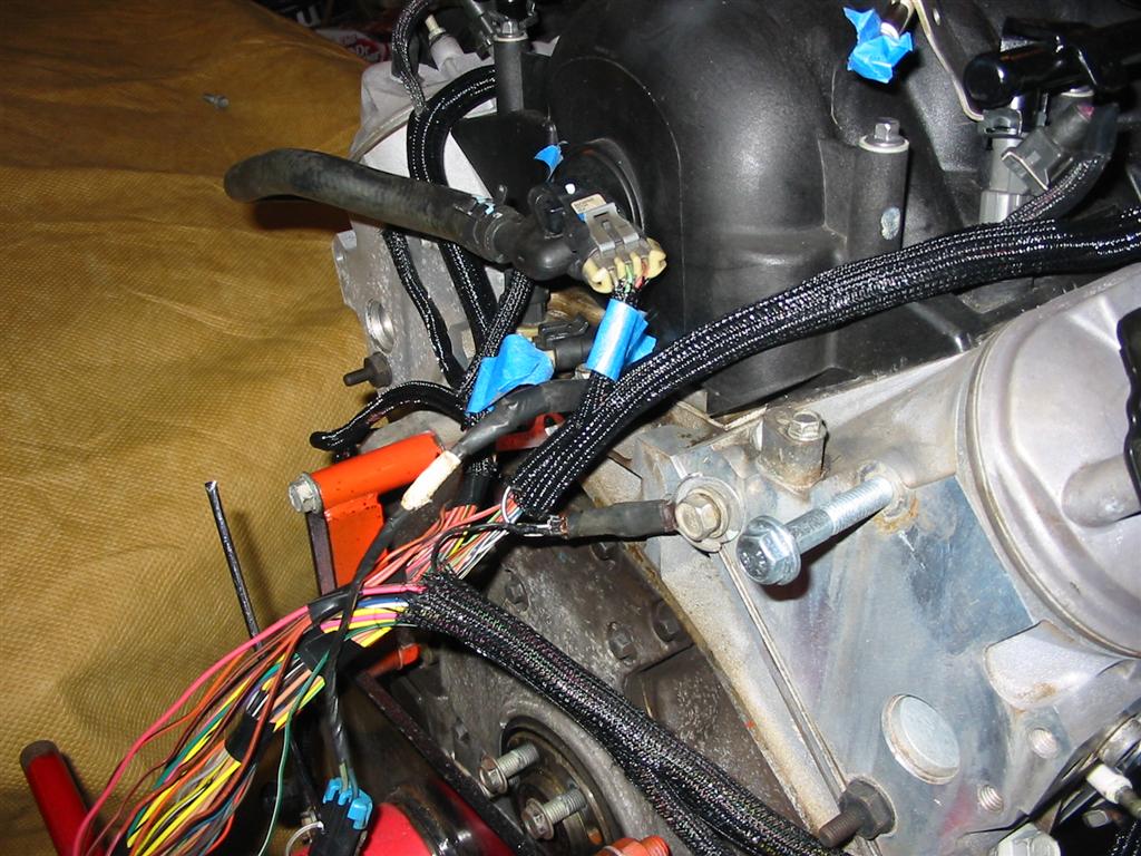
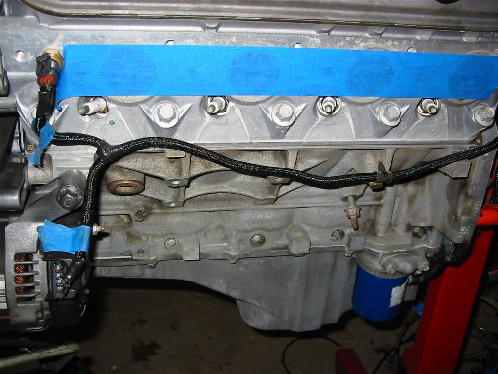
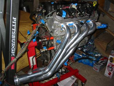
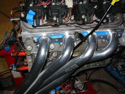
| I decided to hide as many wires as possible by running many of the wires under the headers.
I also ran all the MAF and Throttle Body wires past the front of the head and under the
passenger side headers as well.
|

|

|
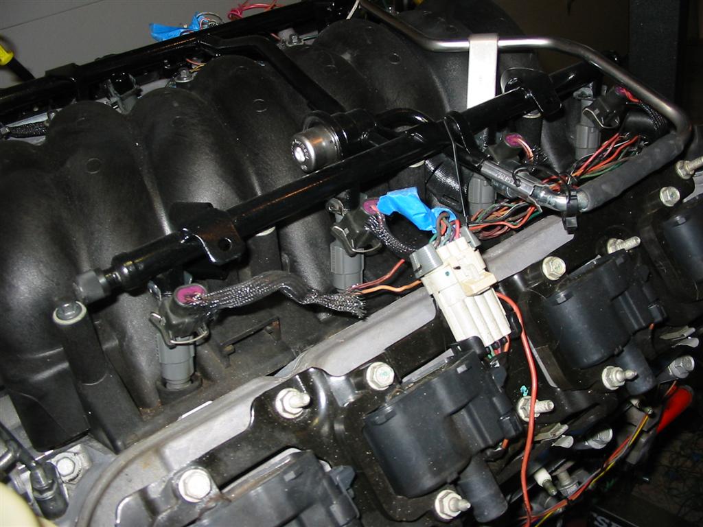
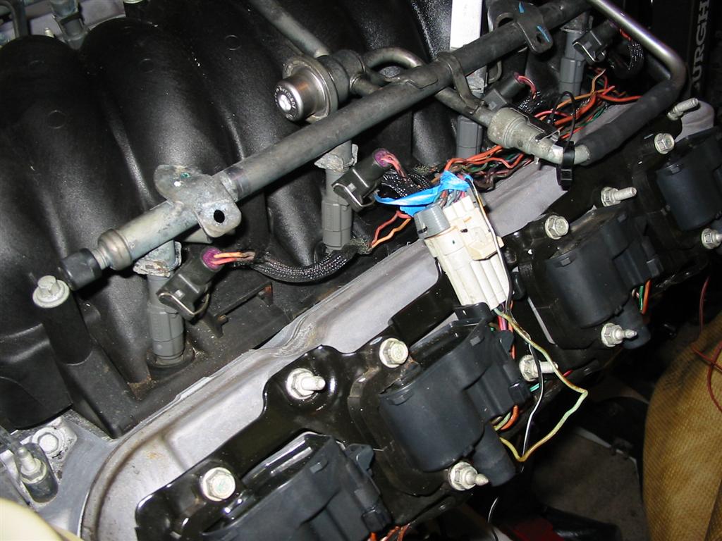
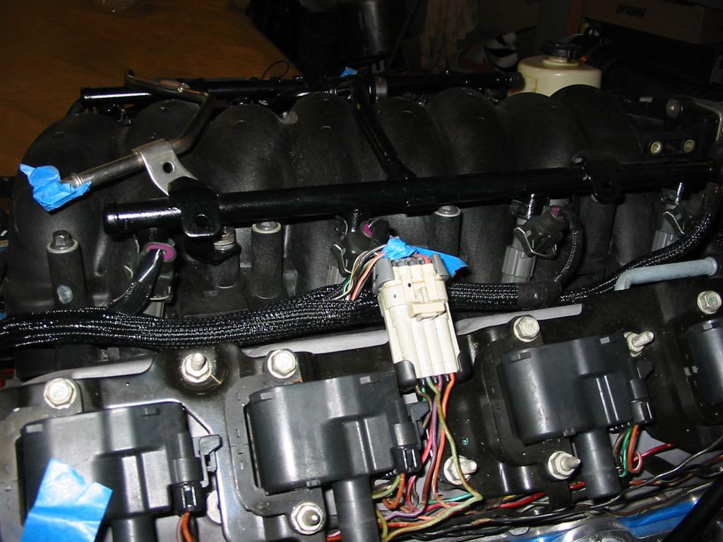
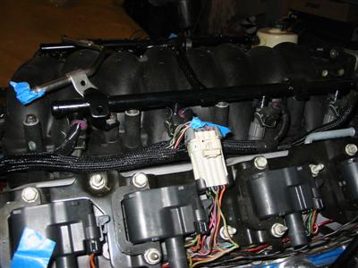
| The only visible wires will be the wires for the injectors and the coil packs. Also pictured
here is the evap solenoid that I am removing from the intake. |
|
|

|
|
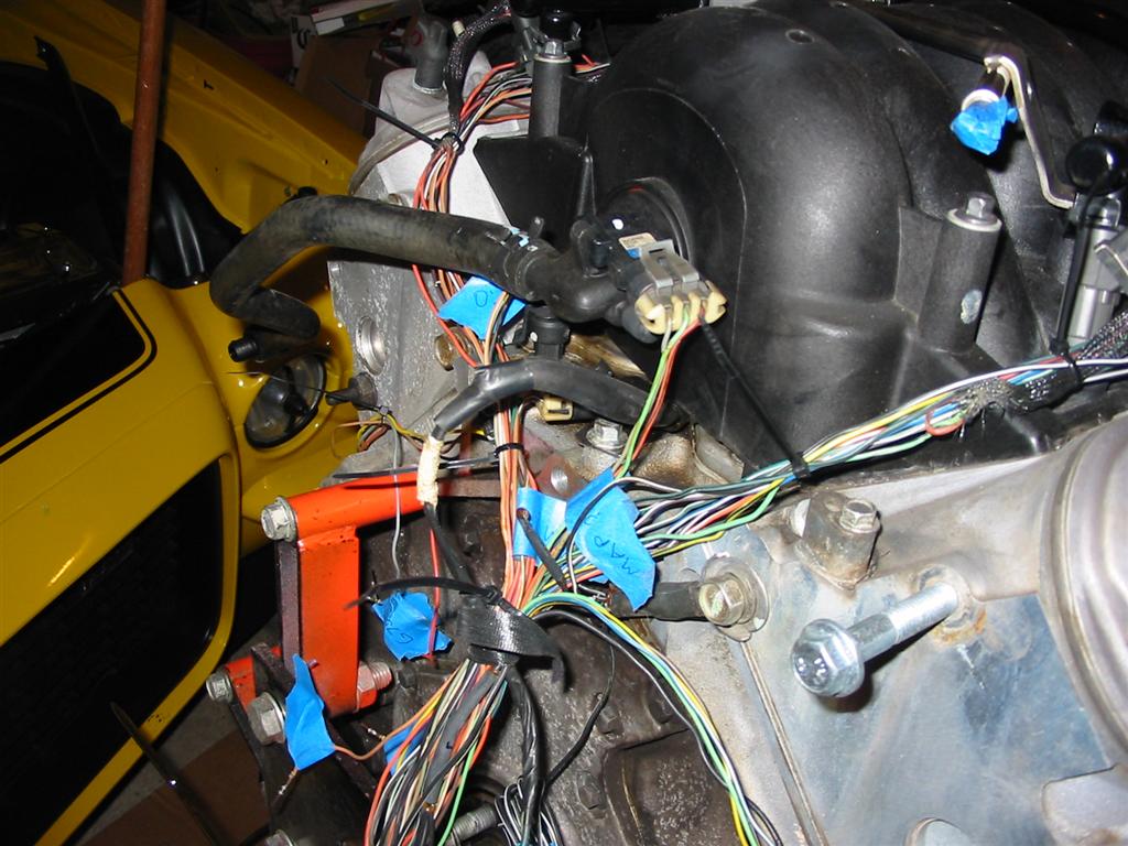
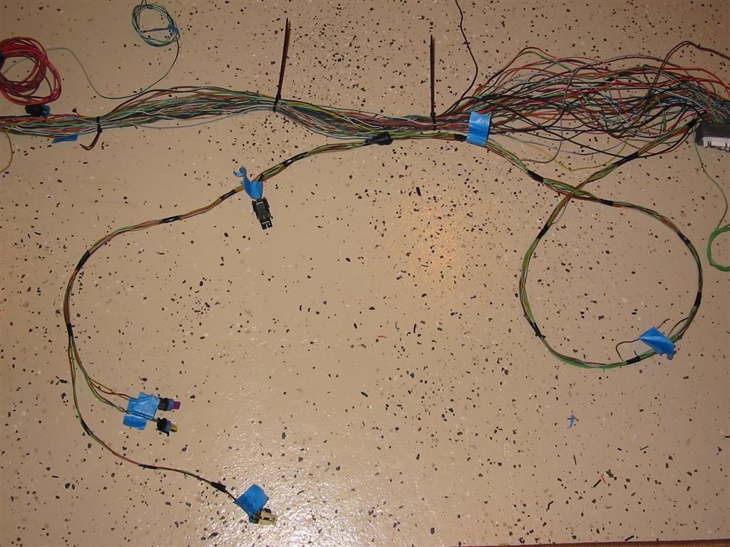
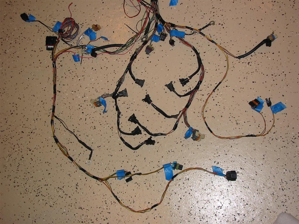
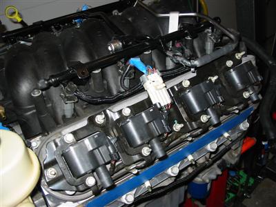
| Here are pictures of the mocked up harness. |

|
|
|
|
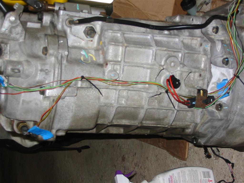
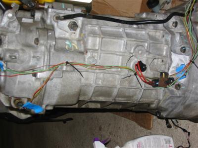
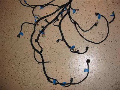
| The transmission harness was also built in a similar fashion. |
|
|
| I removed the harness from the engine and started working on the lengths. Most of the
wires needed to be shortened while some of them needed to be lengthened. I used solder
and heat shrink tubing to extend the necessary wires. |
|
|
|

|
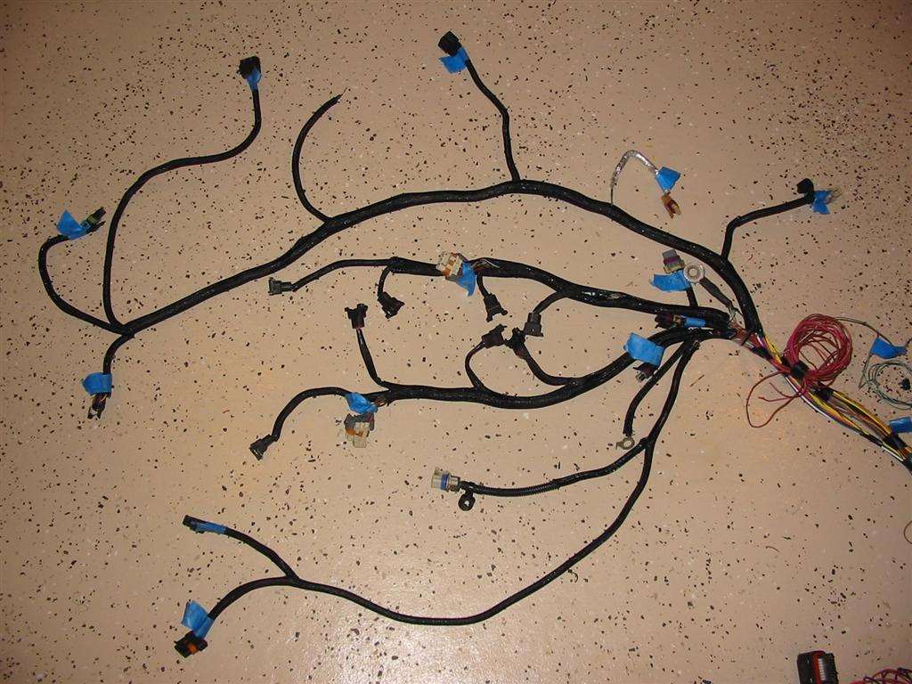
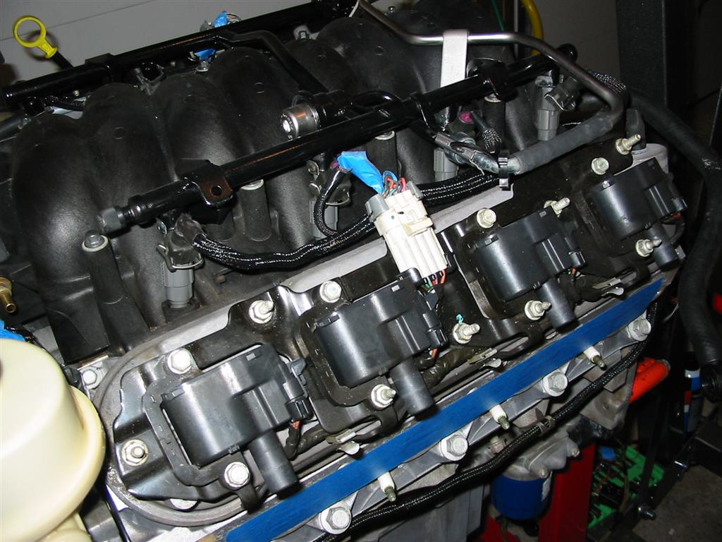
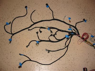
| I used Jegs Flexbraid to cover the harness to give it a modern professional look and then
test fitted the harness to the engine. |
|
|
|

|
|
|

|
|
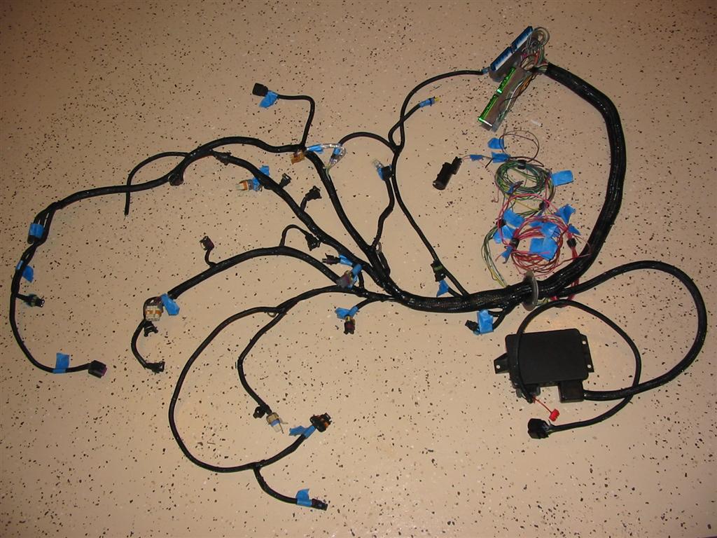
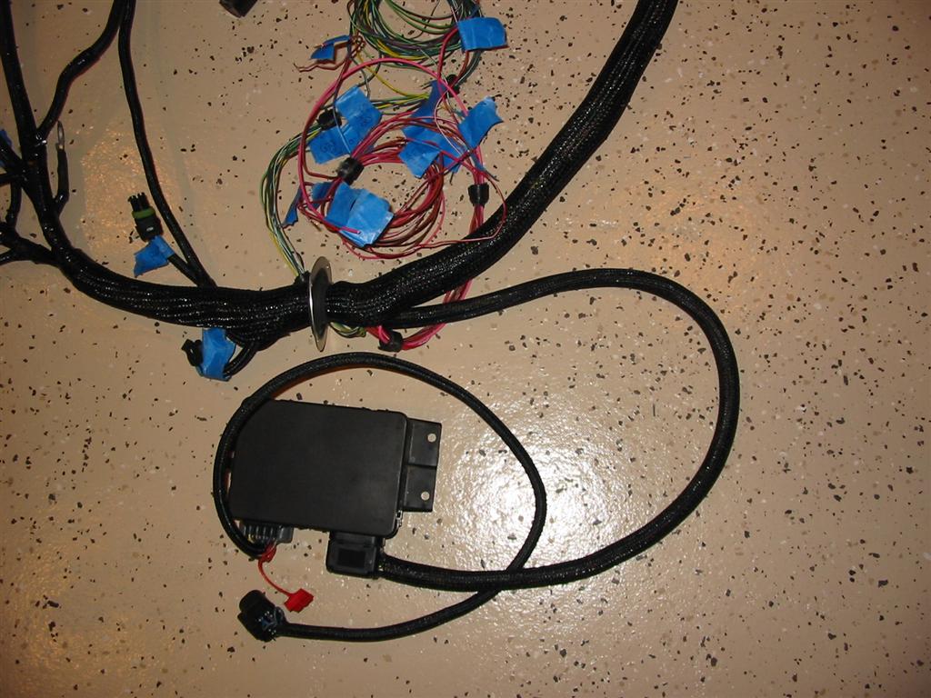
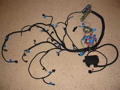
| Here are the final pictures of the harness completed and ready for installation including the
TAC module. |
|
|

|
|