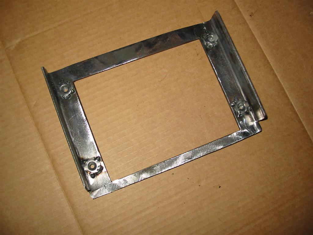
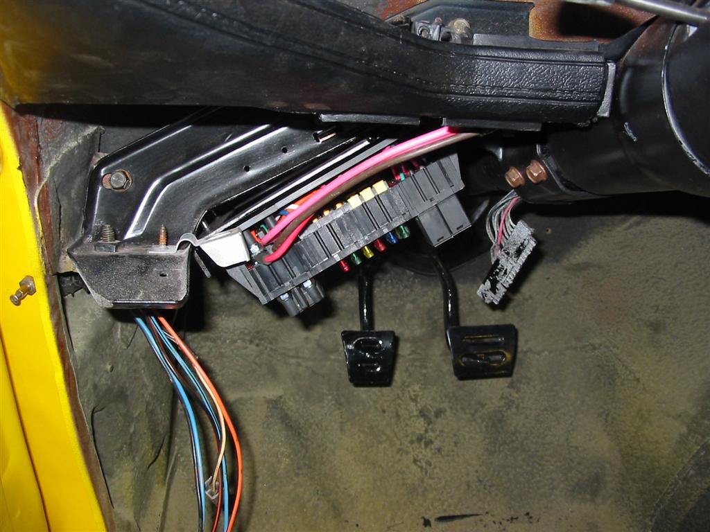
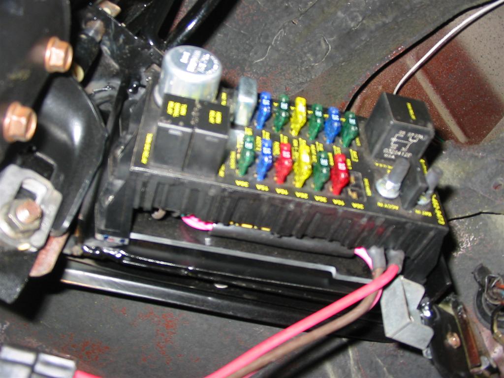
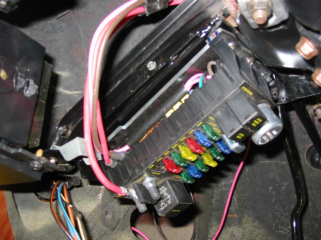
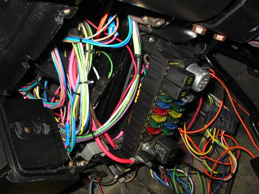
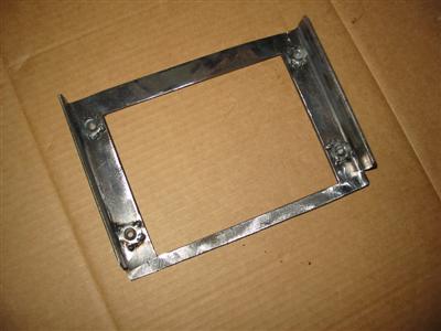
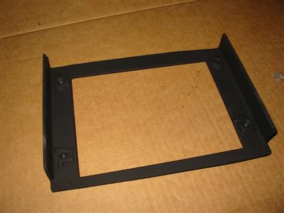
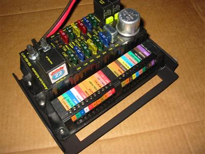
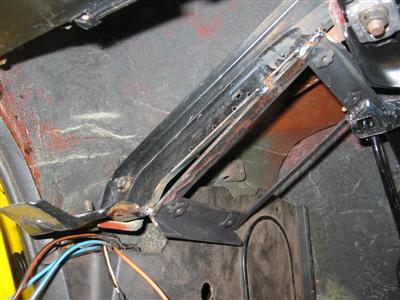
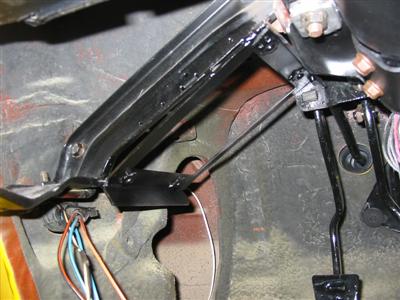
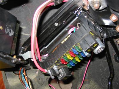
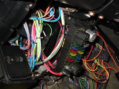
| I decided to mount my fuse box under the dashboard. The new fuse box was a little too
big to fit in the factory location. I made a bracket and welded it to the dash support
and mounted the fuse box to the bracket. |
|
|
|
|
|

|

|
|
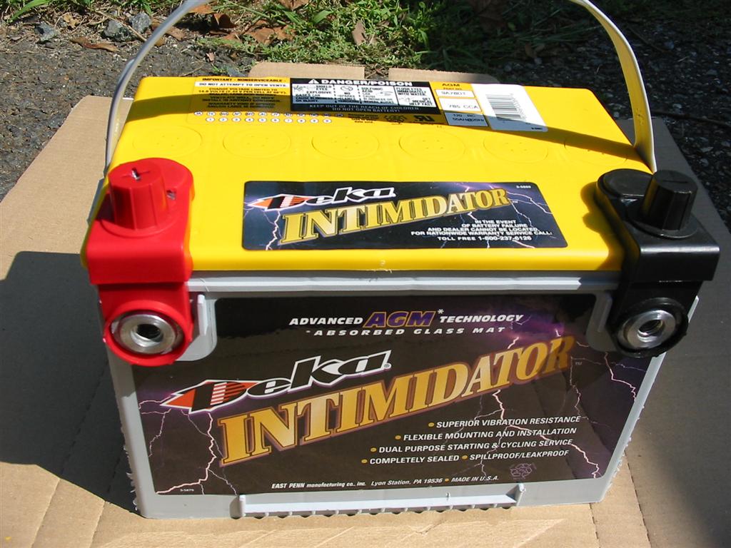
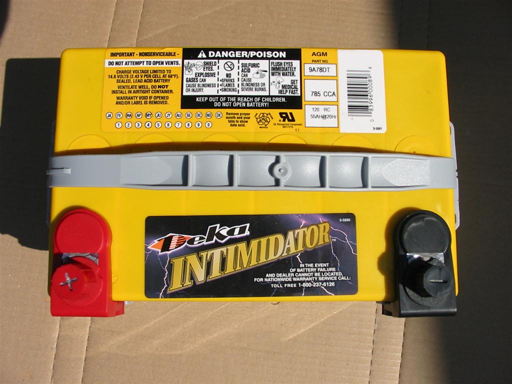
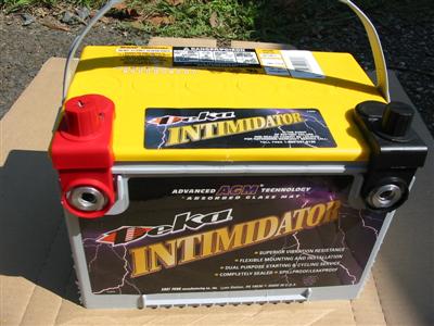
| Here is the battery I am using. After much research, I decided to go with a
Deka Intimidator AGM battery. I wanted an AGM battery and this one was the
best reviewed for the money. I was going to go with a Optima Red Top, but I have heard
mixed reviews on them over the last few years. Also, the Deka was cheaper. The
battery has 785 Cold Cranking Amps. |
|

|
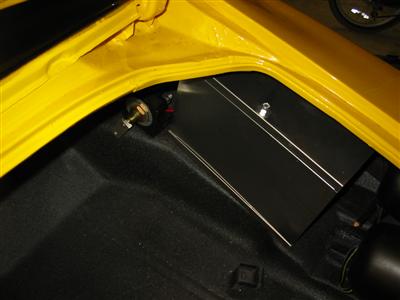
| I mounted the battery in the aluminum box in the trunk and ran the wires. I grounded the
battery to the bumper mount bolt. |
|
|
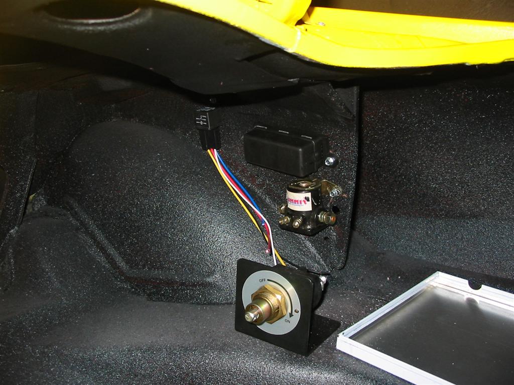
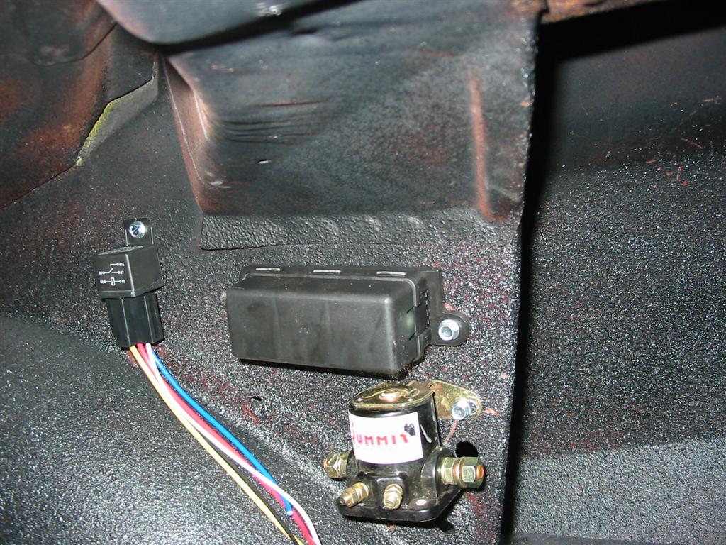
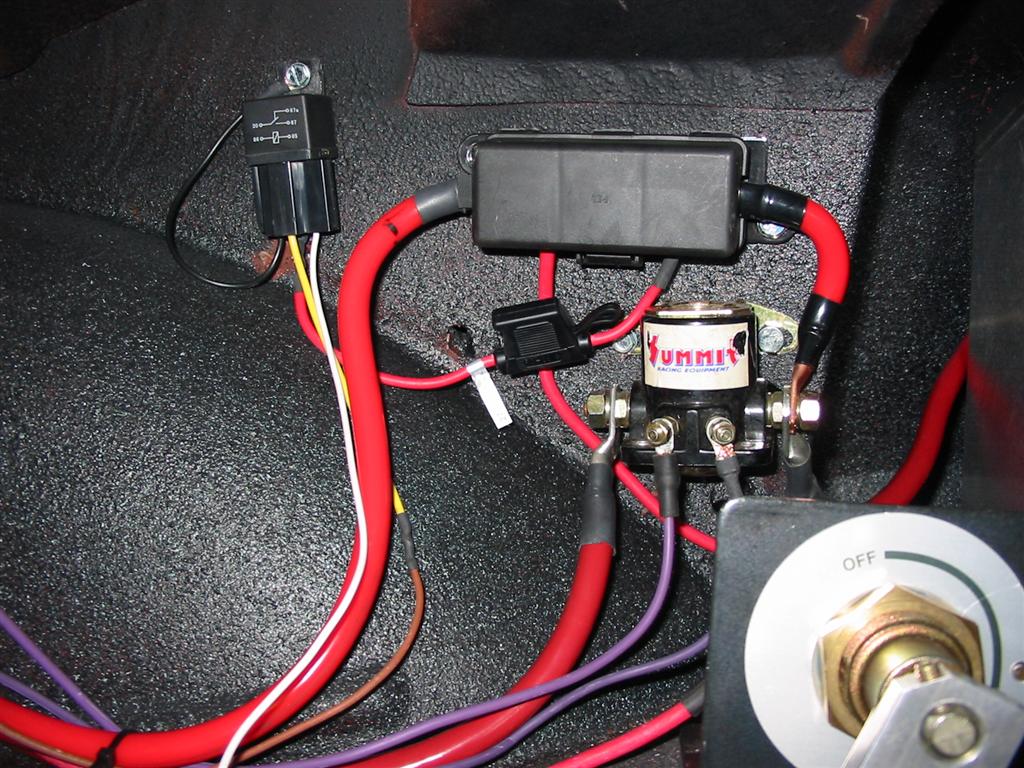
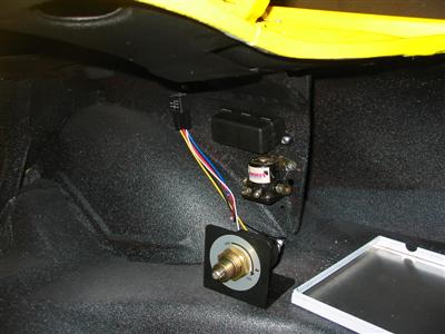
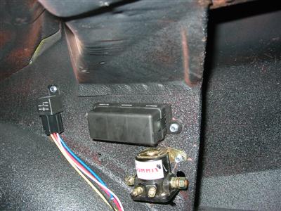
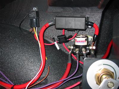
| In this picture are all the components mounted in the trunk. The top item is the
Maxi Fuse that came with the Highway 22 kit. This fuse protects the main wire and the
alternator wire. The bottom the item is a Ford starter solenoid. This allows the
large starter wire going the length of car to only be live when the car is starting. The
relay in the upper left corner is a relay for the fuel pump. The large switch on the
bottom is the Master Disconnect switch. This feeds the fuse box and allows the engine
to be shut down while it is running. |
|
|
| Here is a wiring diagram for the trunk mount system. |
|
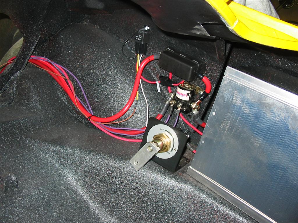
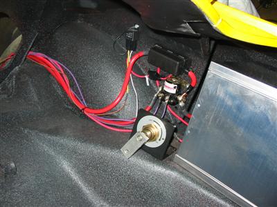
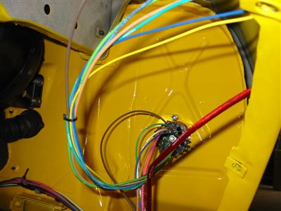
| Here is everything hooked up. |
|
|
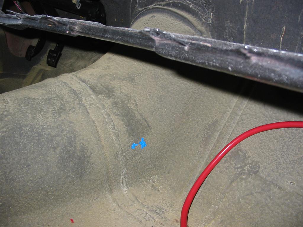
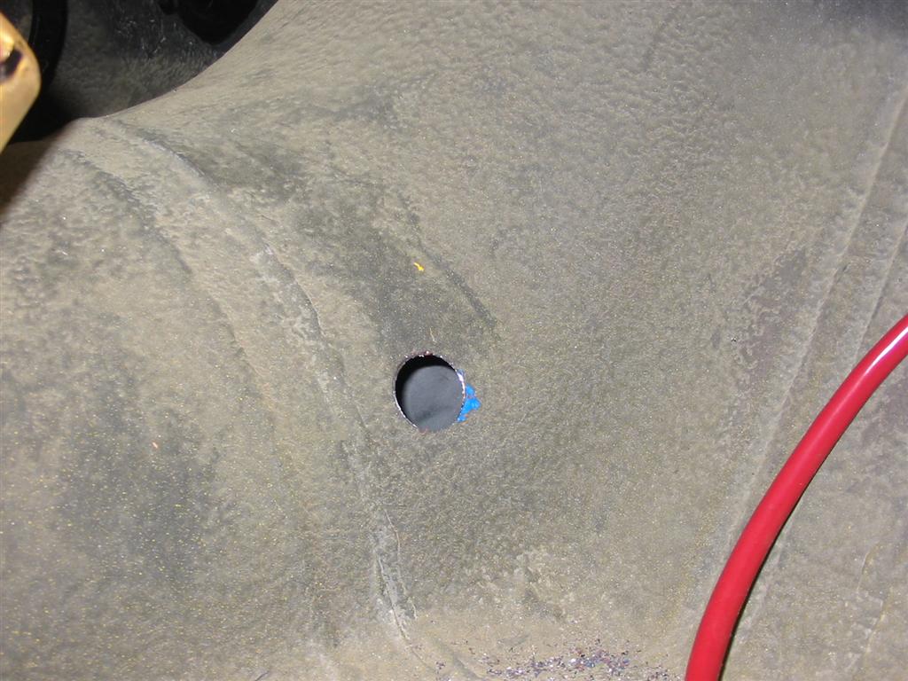
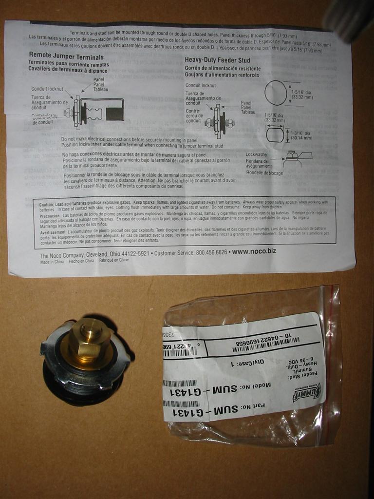
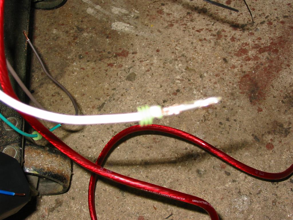
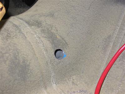
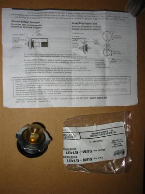
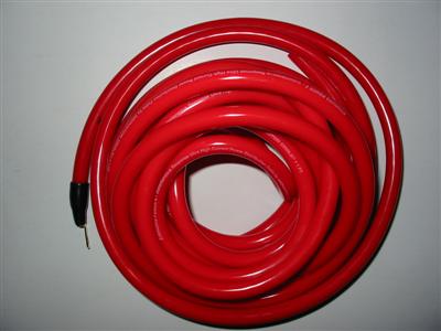
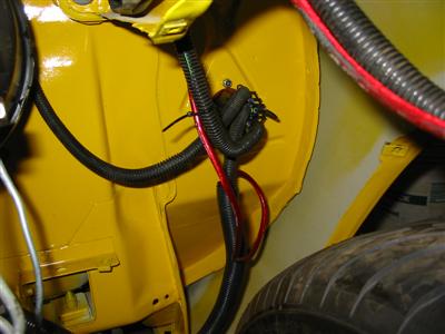
| I ran the large starter wire and the solenoid activation wire through the car. I used
a bulkhead fitting for the large wire and a grommet for the smaller wires. |

|
|
|

|
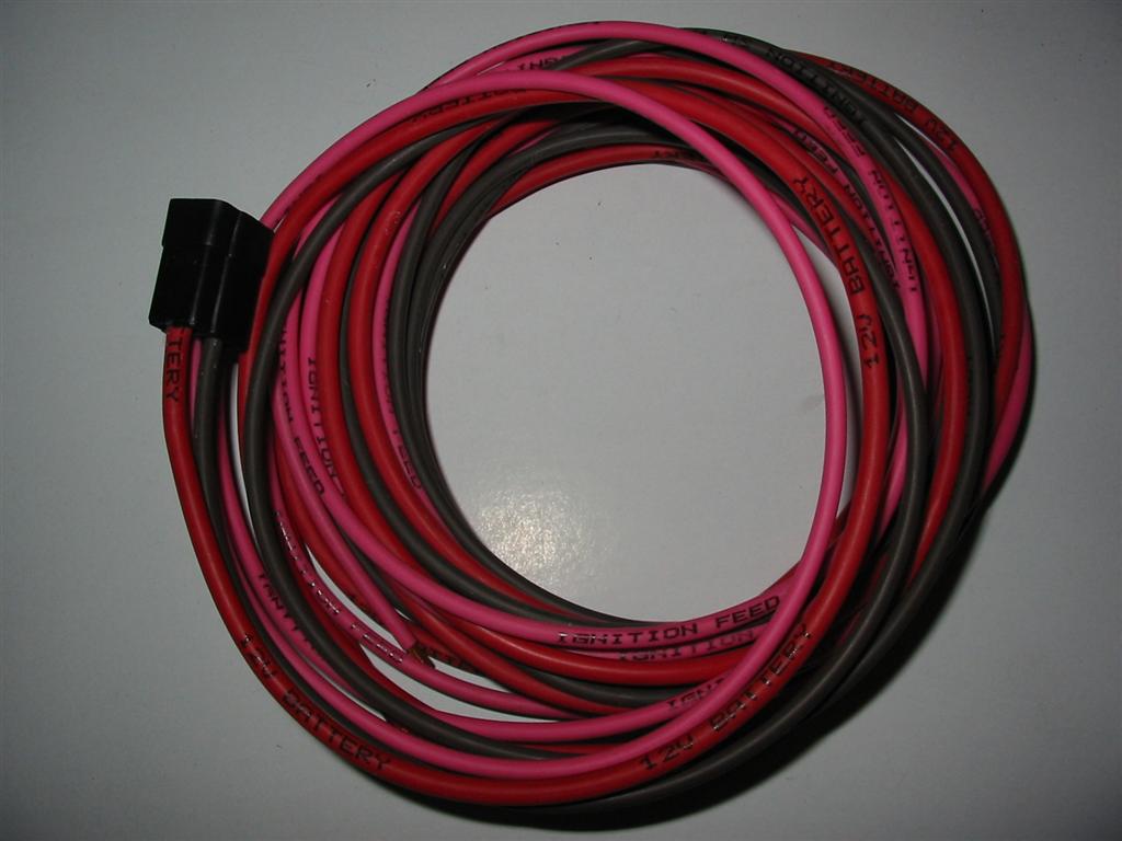
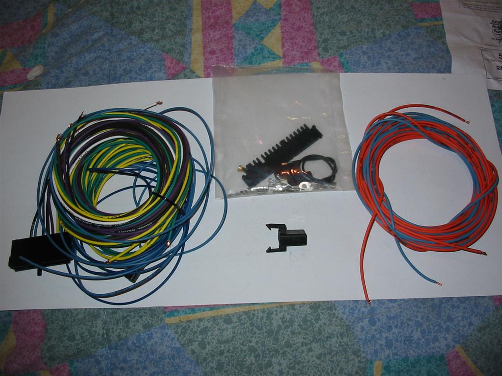
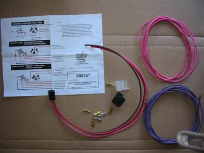
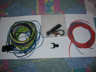
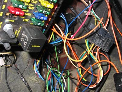
| Here are the wires that the kit gives you for the ignition system. These plug into the
GM ignition switch and the other end plugs into the fuse box. |
|
|
|
|
|
|
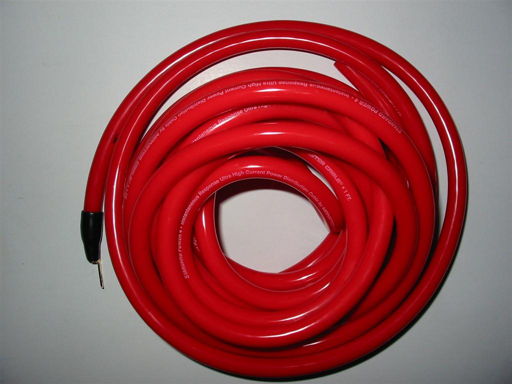
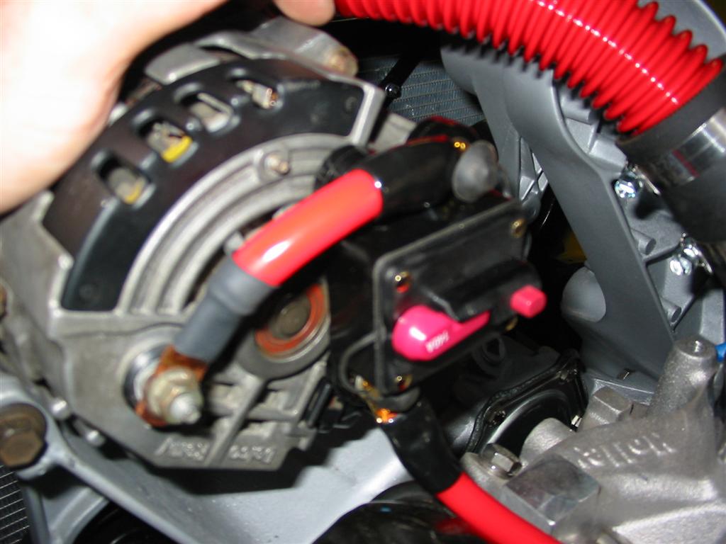
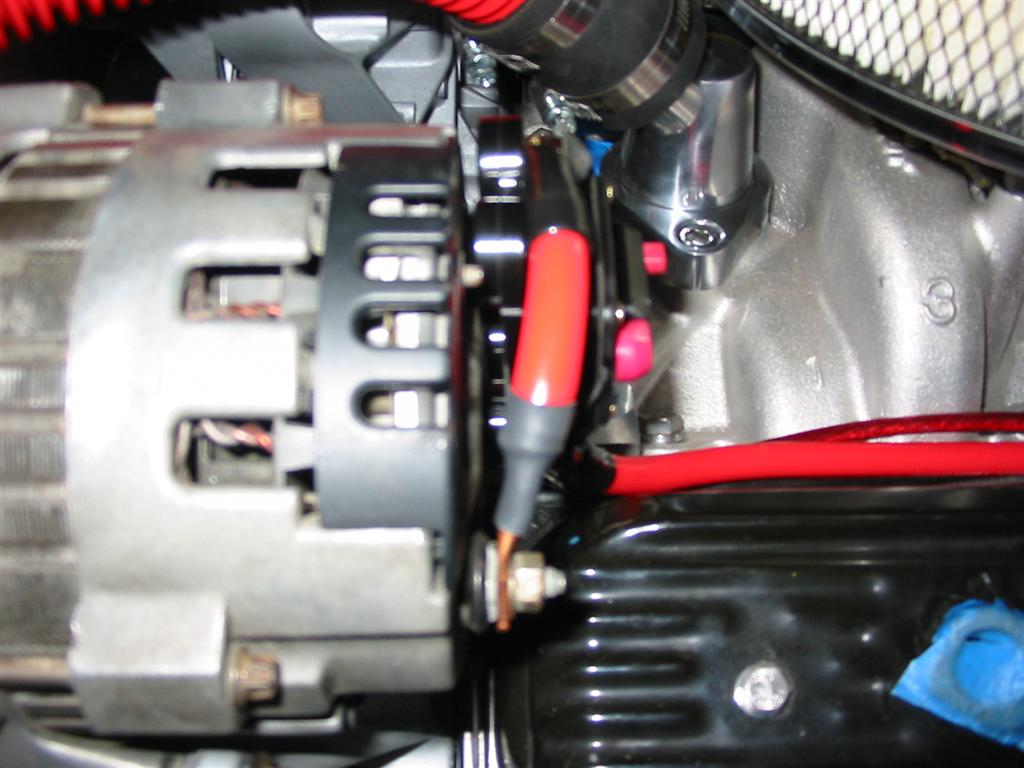
| I then wired up the alternator. I ran 4 gauge wire from the alternator to the fuse in the
rear of the car. I also mounted a circuit breaker on the alternator and used this to
protect this wire. The alternator is the 100 amp unit that came with the serpentine system. |
|

|

|
|
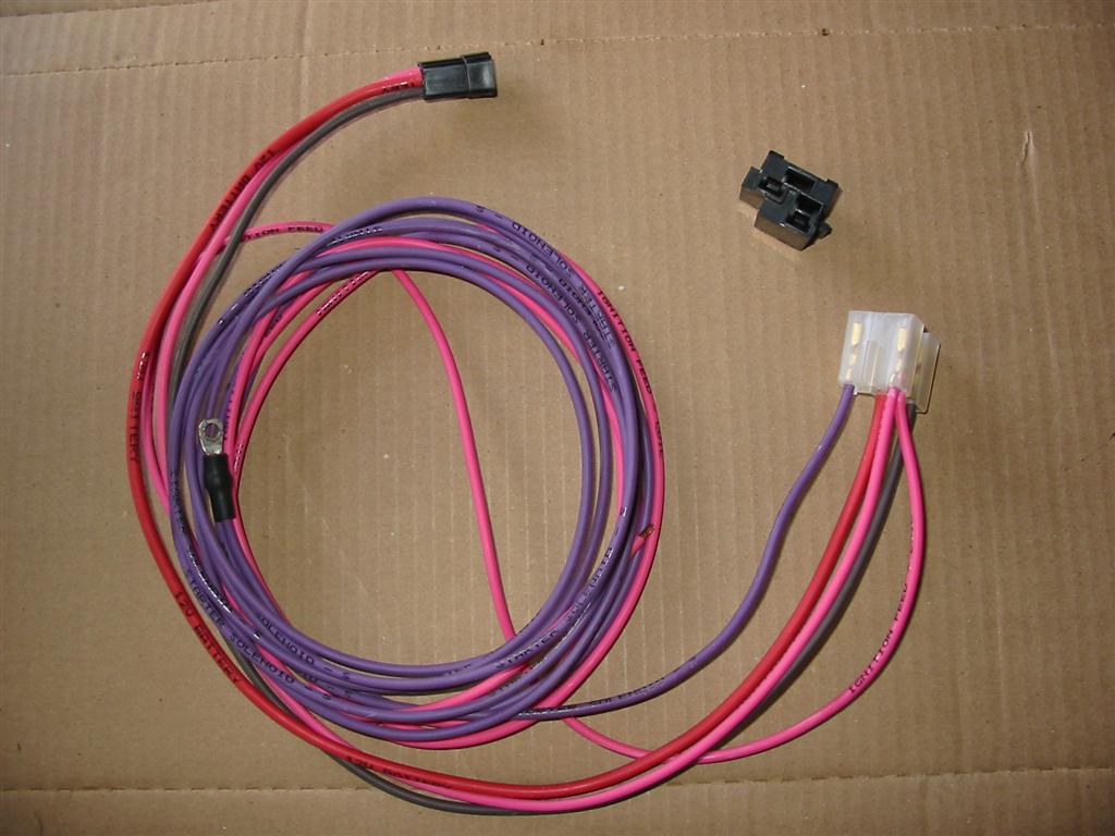
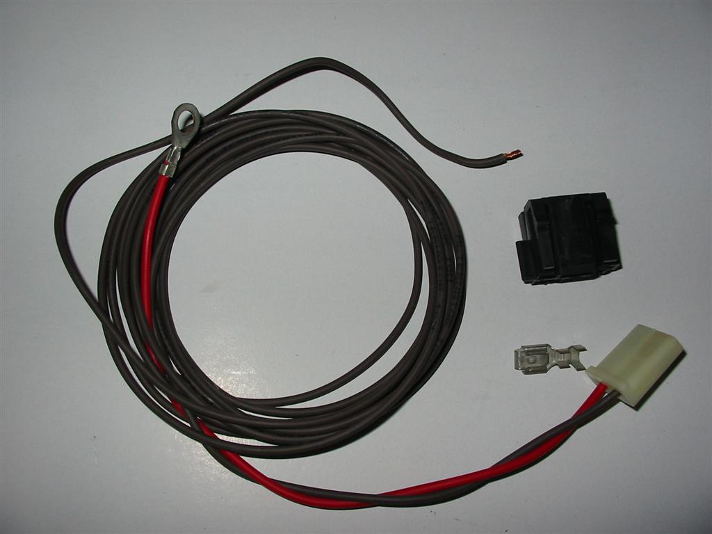
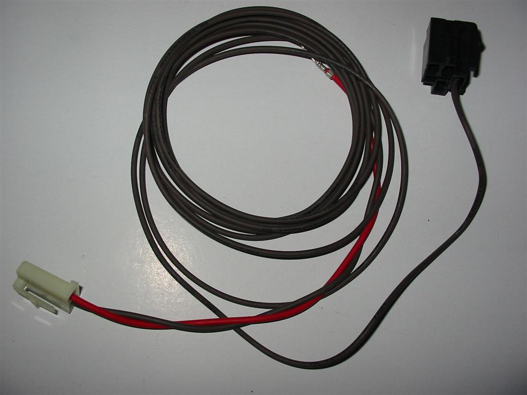
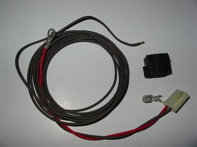
| Here are the wires that come with the kit for the Alternator. One side plugs into the
alternator and the other side plugs into the GM ignition switch. The kit originally
comes with the older style plug for the alternator. I changed the plug to fit in the
newer style alternator. I also needed to put a resistor inline for the exciter wire
since I do not have an idiot light hooked into the circuit. |
|
|
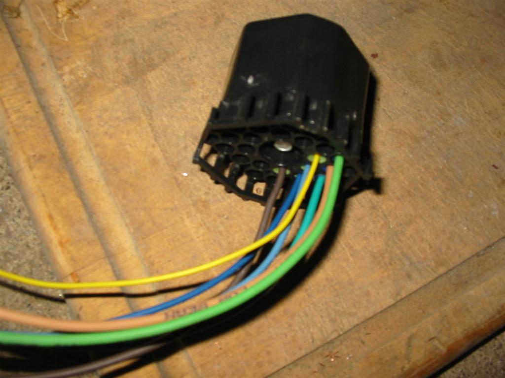
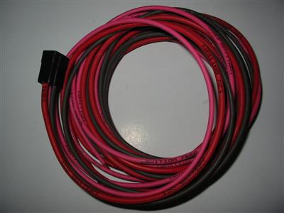
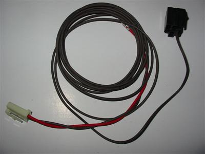
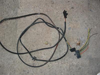
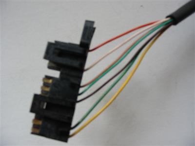
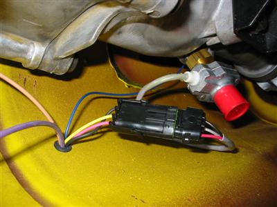
| Here is the harness for the light switch. |
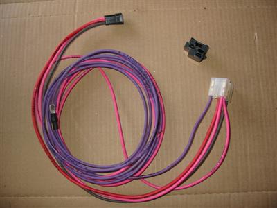
Here is the harness for the column and the brake lights. |
|
|
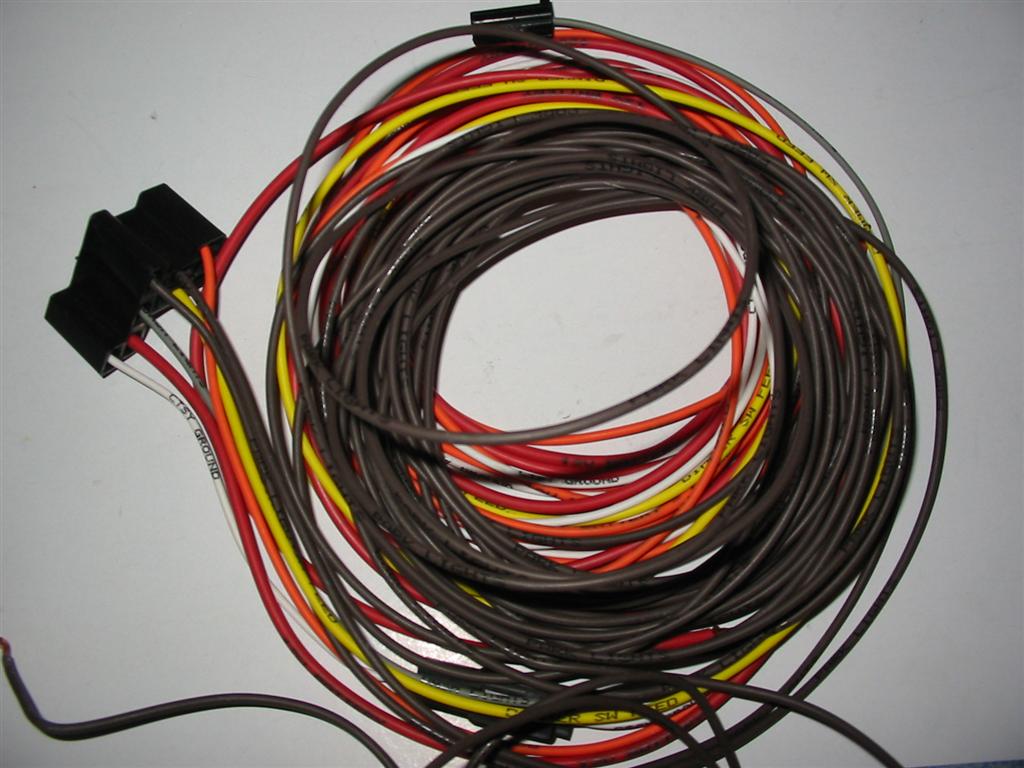
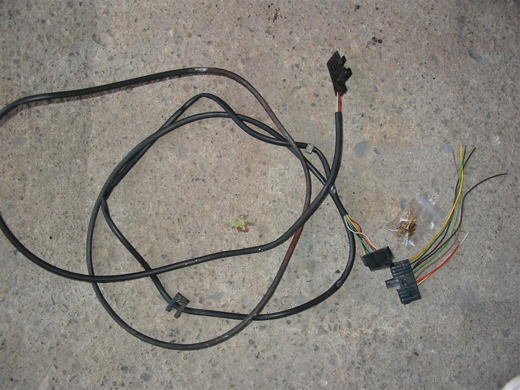
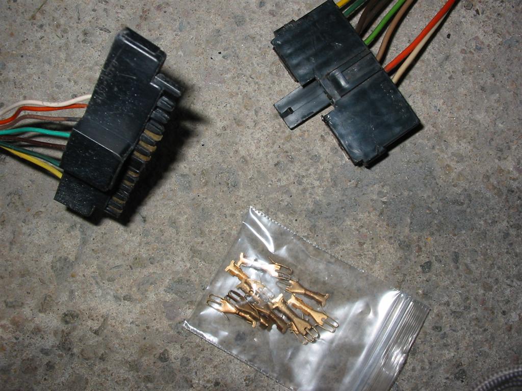
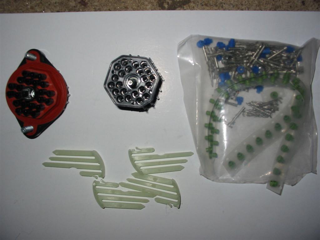
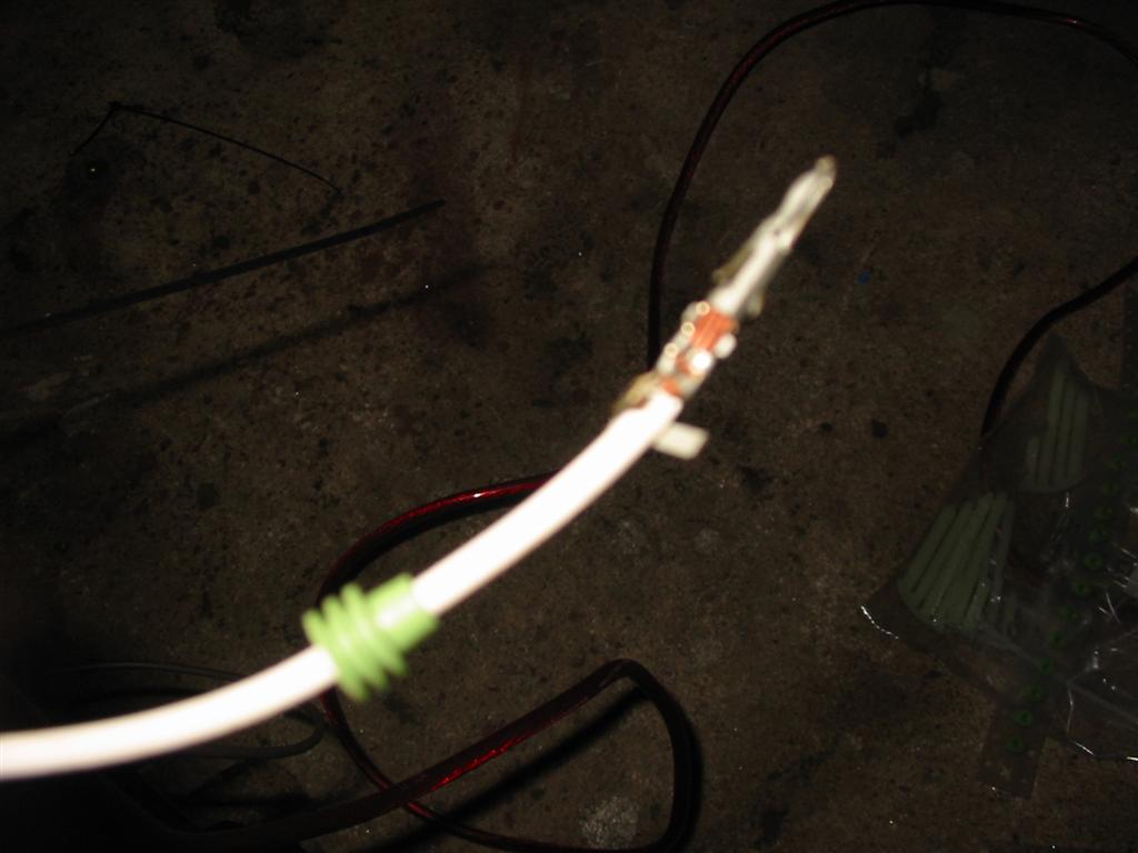
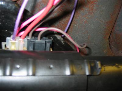
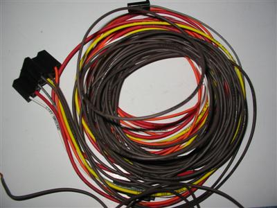
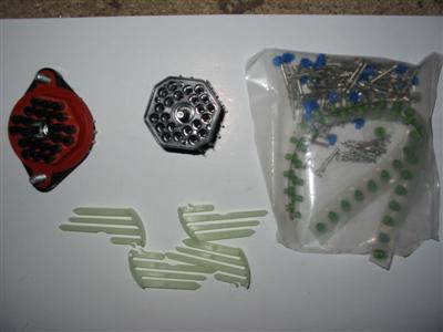
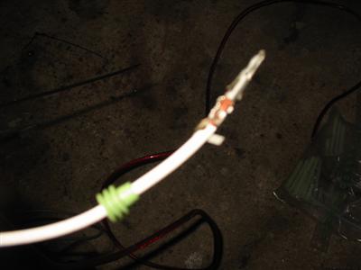
| Here is the factory harness for the rear lights. I reused this harness and the original plug.
I purchased the correct connectors to change out the harness plug. |
|

|
|
|
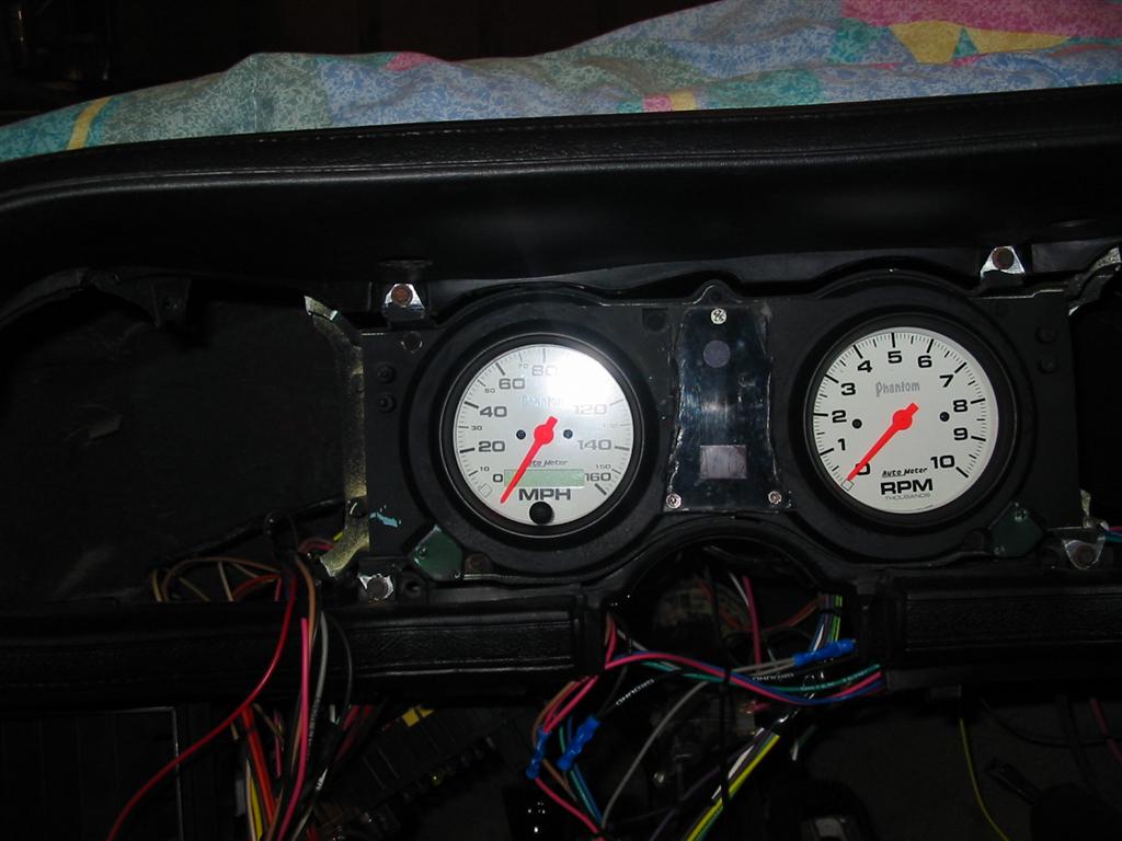
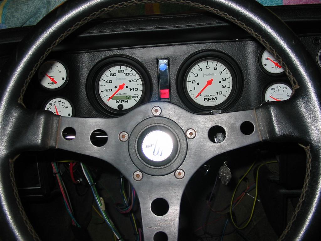
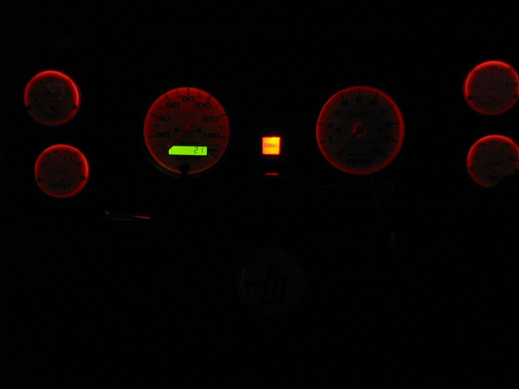
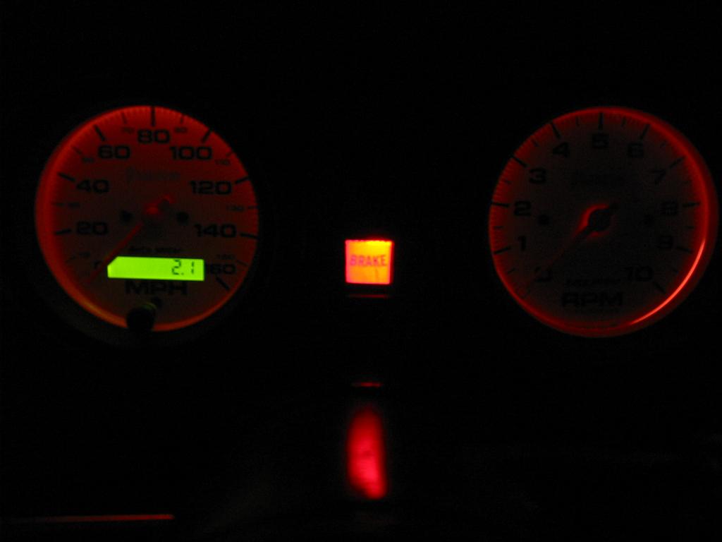
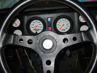
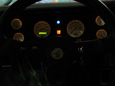
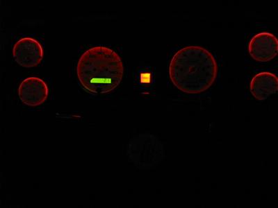
| Here are shots of the modified gauge cluster being installed. I decided to use red
lighting for the gauges. |

|
|
|
|

|
|
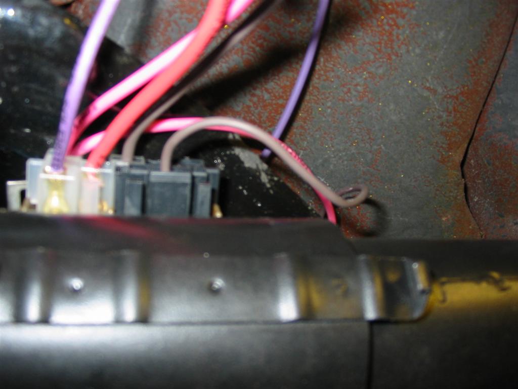
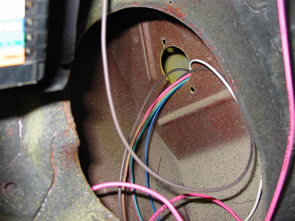
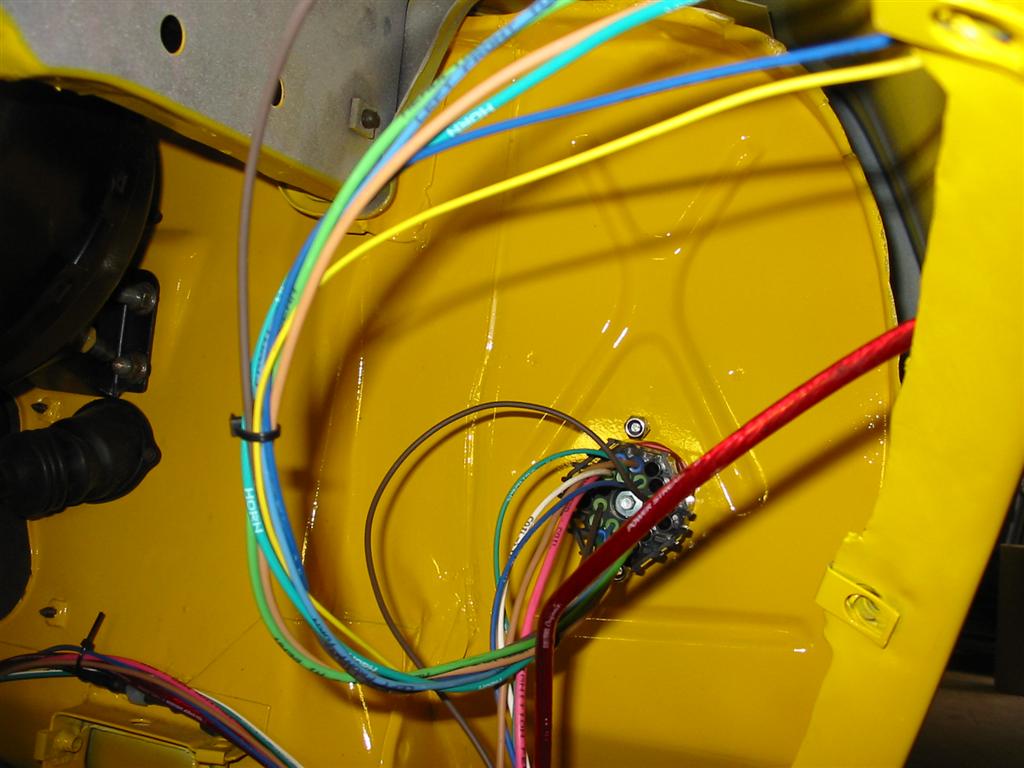
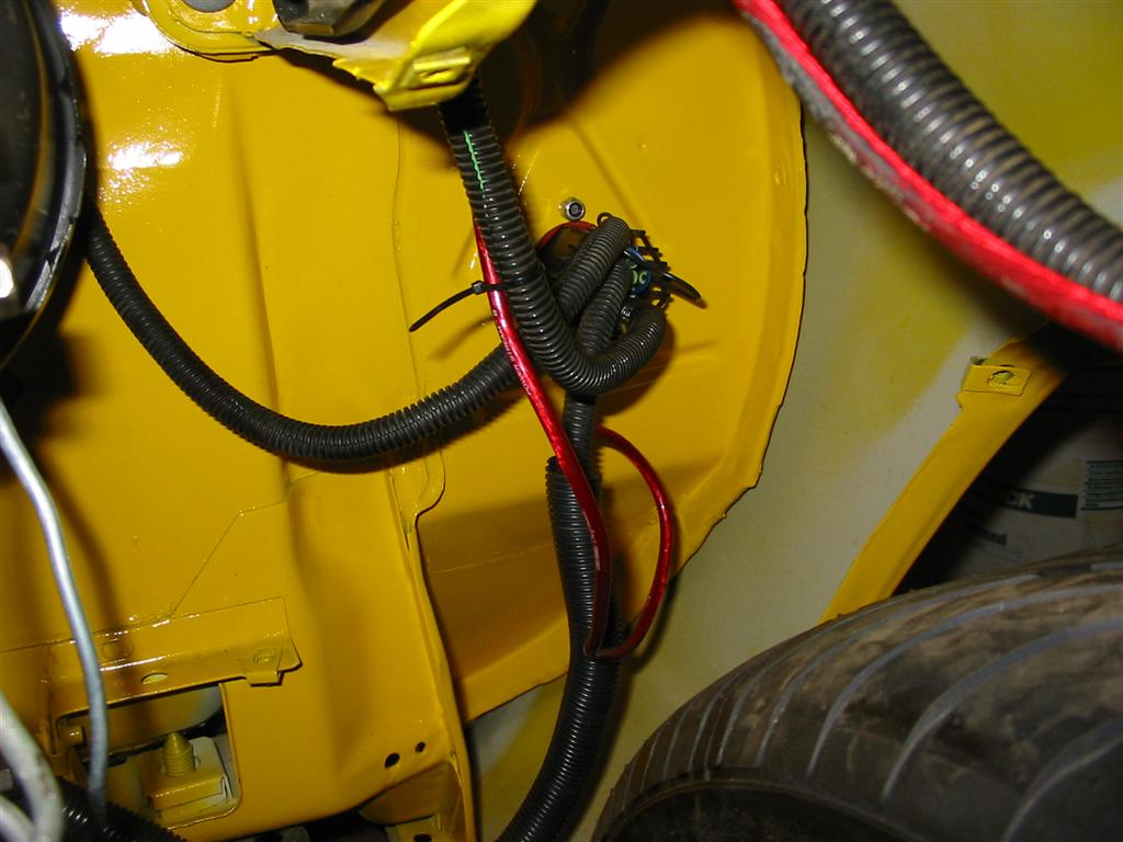
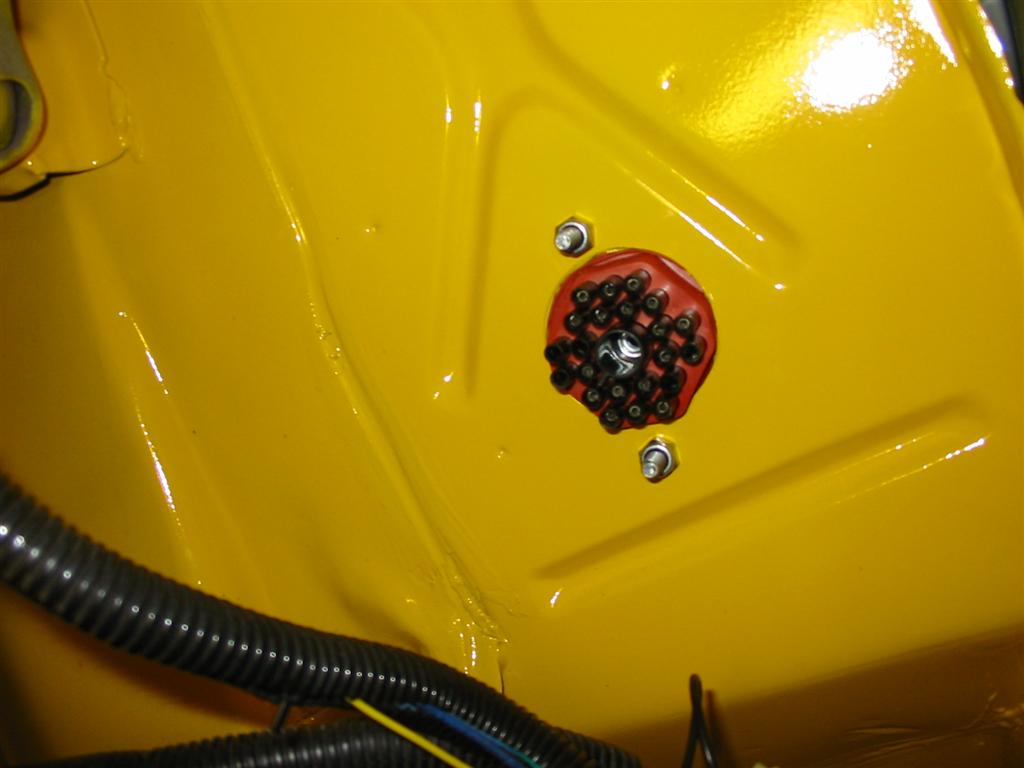
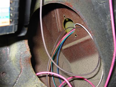
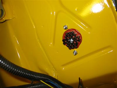
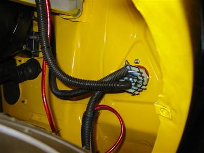
| I ran the wires through the cowl into the inner fender. I used an American Autowire
22 port bulkhead. The wires are installed into the bulkhead using the supplied weather
proof connectors. Once the connector was wired up, I used silicone sealant in the unused
holes and dielectric grease on the inside of the plug. |
|
|

|
|

|
|
|
|
|
|
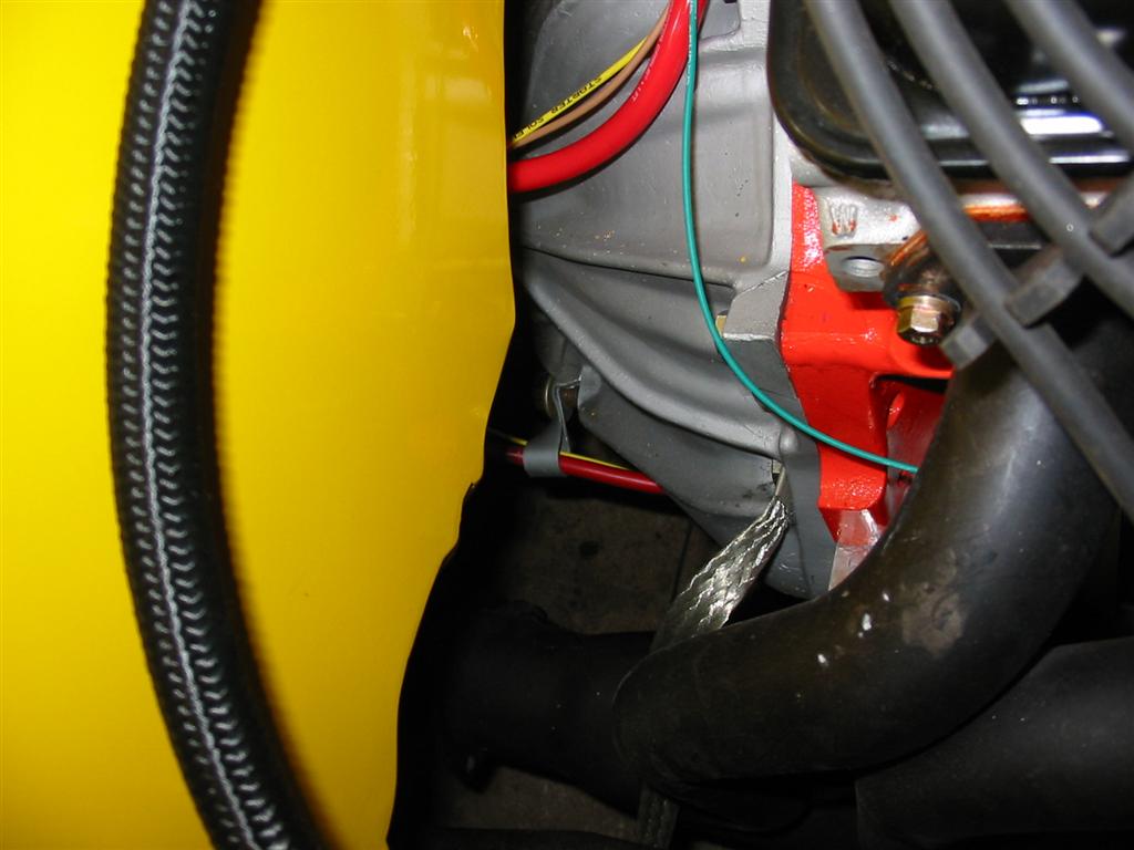
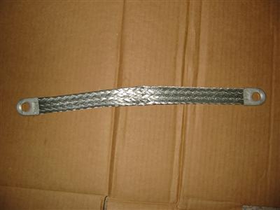
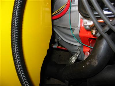
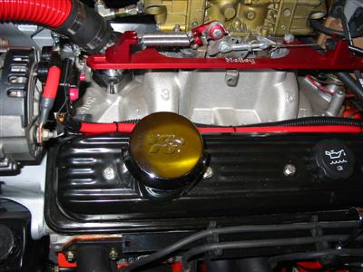
| I purchased a generic ground strap and mounted one side to the right side of the bellhousing
and the other side to the frame. |
|
|
|
|
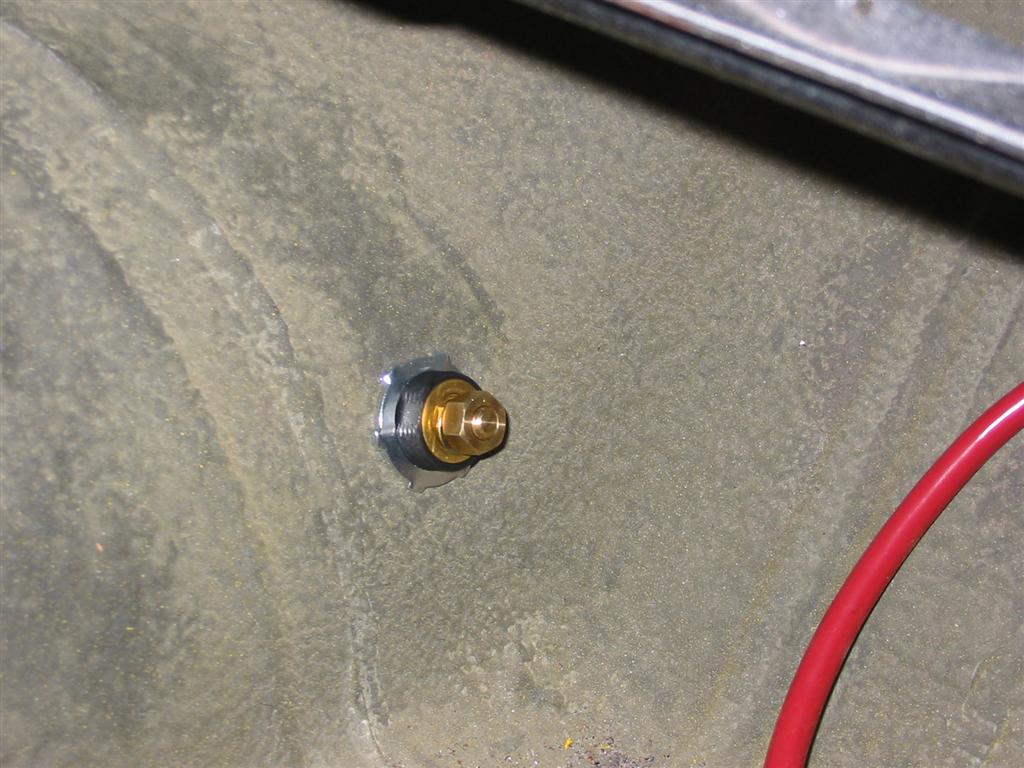
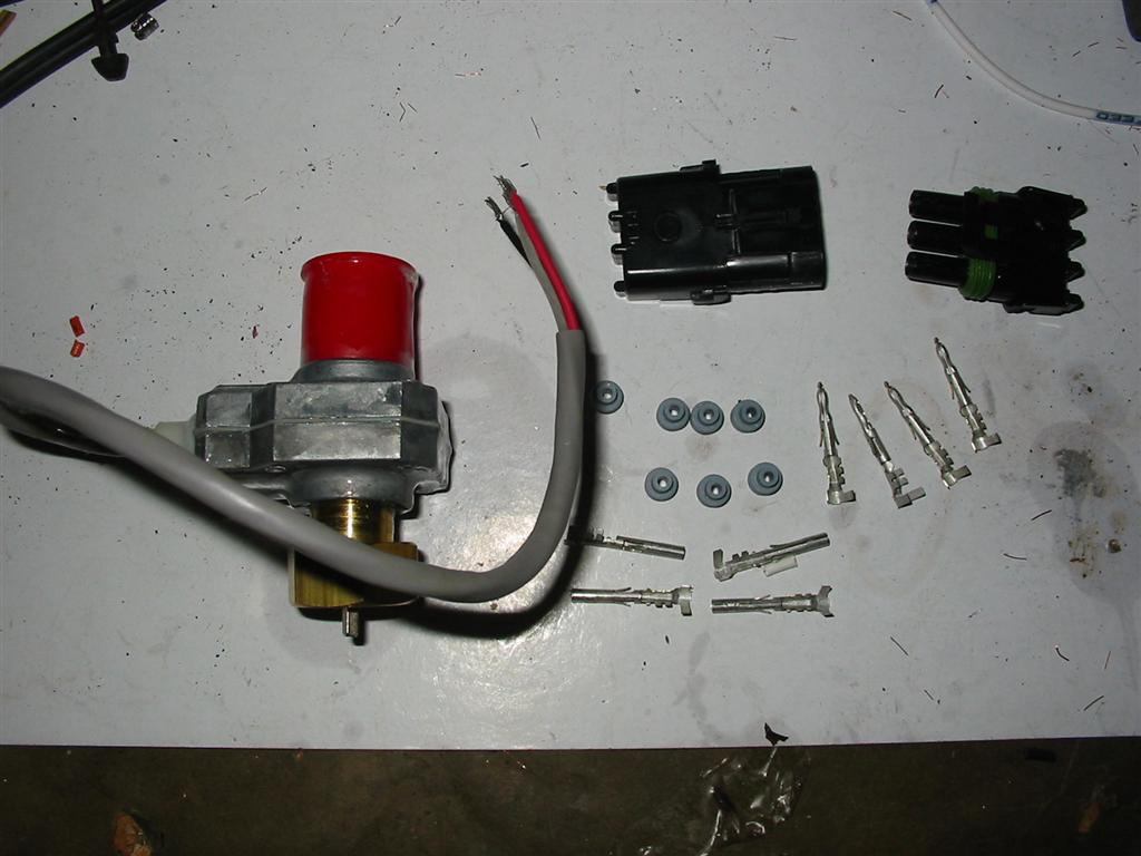
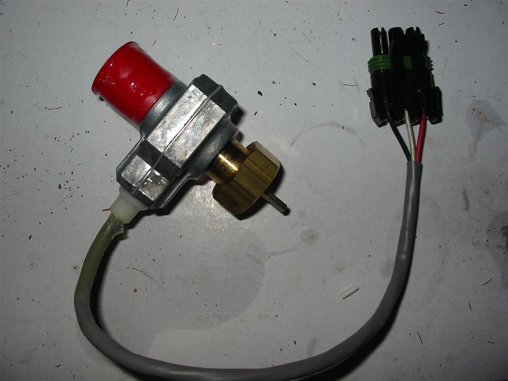
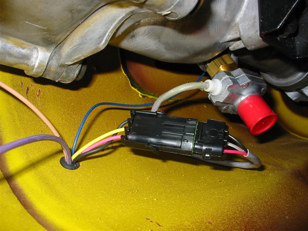
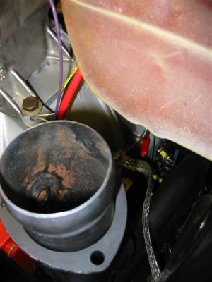
| Since I am using an electric speedometer, I needed to install a speedometer sending unit.
I also purchased a weather pack connector to connect the sending unit to the gauge. |
|
|
|
|
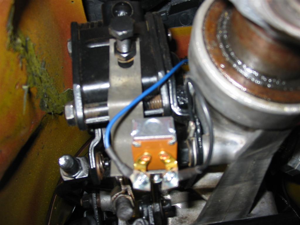
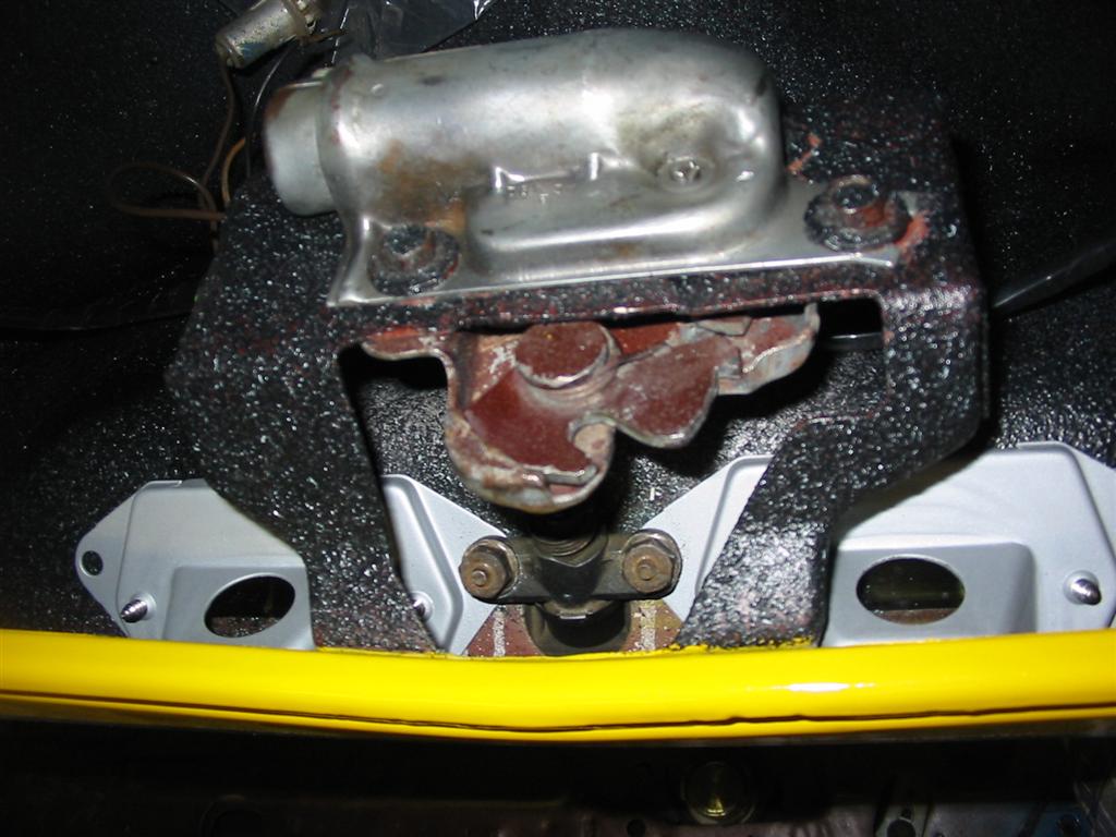
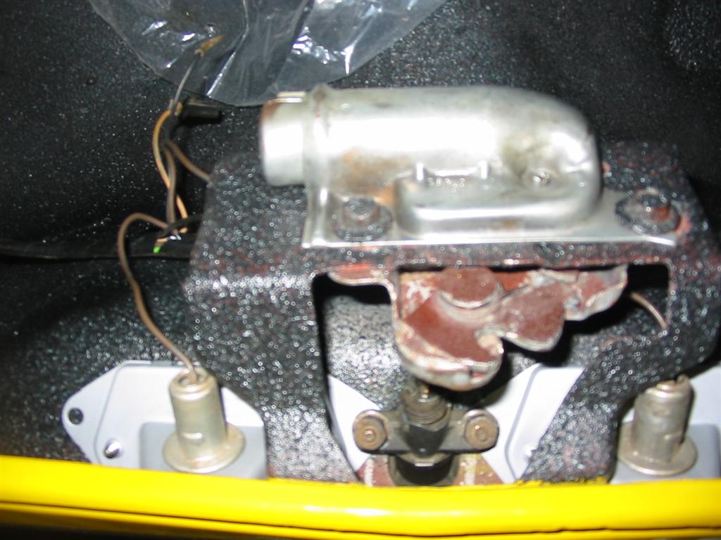
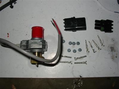
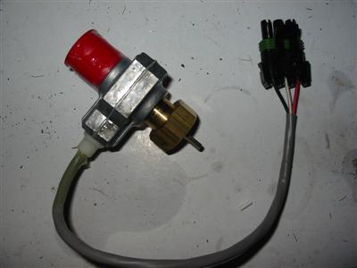
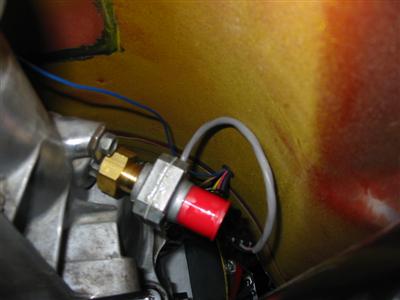
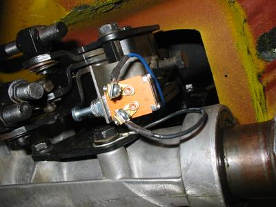
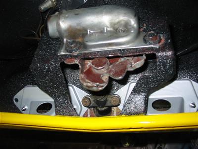
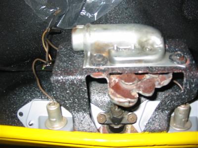
| I am unable to use the factory back drive unit for the reverse lights due to the design
of the headers. I decided to buy the appropriate backup light switch for the Hurst
shifter. Here are pictures of the switch installed. I decided to use a relay in the
car and activate the lights using ground activated circuit. |

|
|
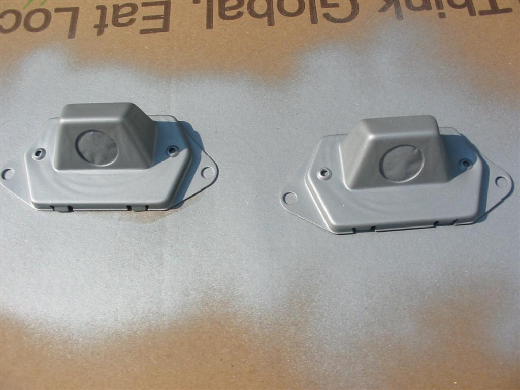
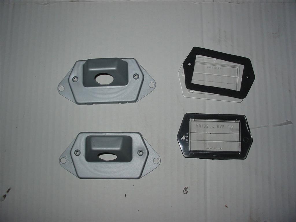
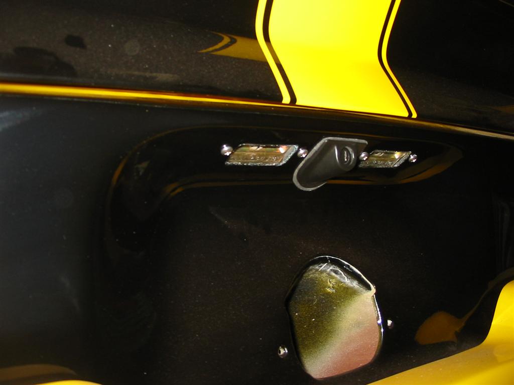
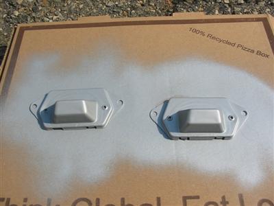
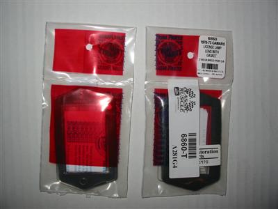
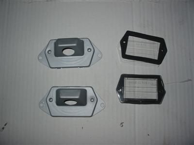
| I also cleaned up the rear license plate light housings and painted them before installing
them. I purchased new lens for the lights because the originals were yellowed. |
|

|
|
|
|
|

|
|
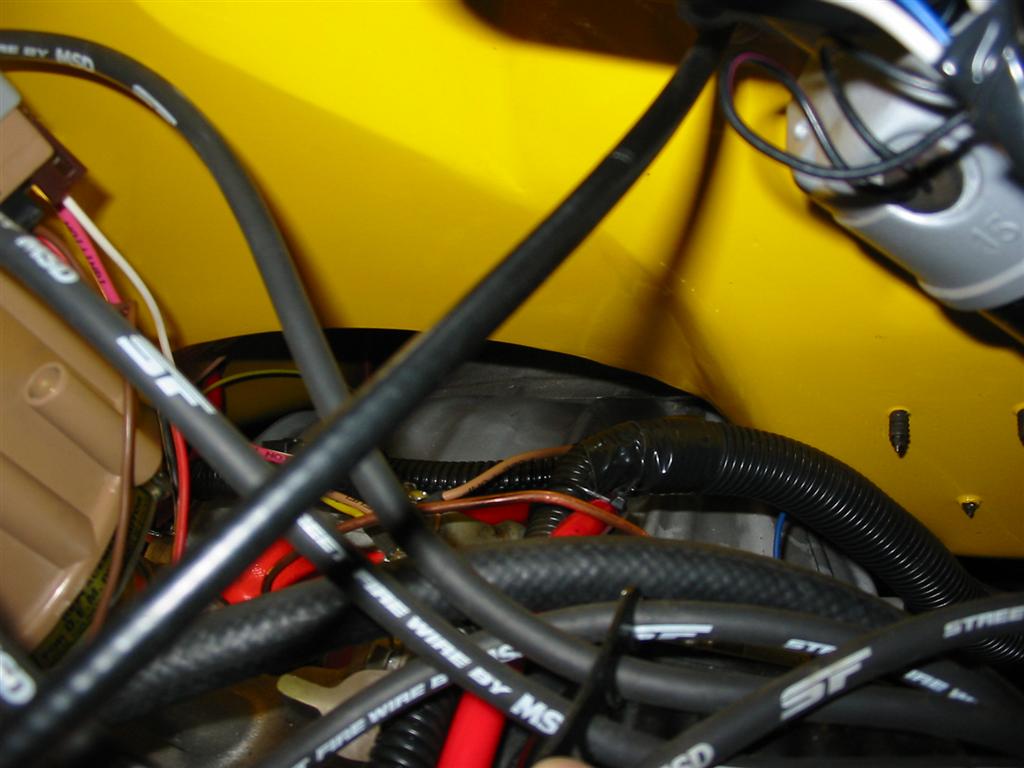
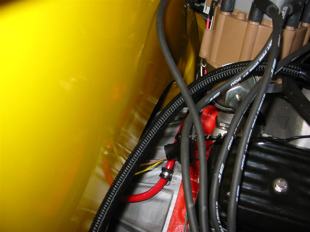
| Here are pictures of finished harness. I used convoluted tubing to hide all the wires in
the engine bay. The wires on the inside will be hidden behind the kick panel. |
|

|

|
|

|
|